Searching math for circuit design, it's clear there are more than several ideas about the meanings of various tube specific terms. Even some of the more authoritative (looking) texts seem not to agree.
eg. Today I've been searching for formulae to understand and work out requirements for a power amp circuit I want to do and find Ra, ra, Ri, fi, Rp and rp used willy-nilly for the same thing.
I know I've been guilty of ignoring the differences and have seen them all used so many ways now I can hardly remember what the original meanings are.
European data sheets often use Ri for Rp and I've seen some use ri or rp for the same thing.
Looking for clear definitions I find most Googled online glossaries don't contain any, or more than one of them. Even the Radio Designer's Handbook (RDH3) only has Rp.
May I ask for some clarification?
Thanks
Standard practice is for lower case letters to be for AC parameters. A subscript is used to qualify them. Until word processors, the use of subscripts was a problem, and sometimes a capital letter with a lower case subscript was used instead.
Capital letters are used for DC (static) parameters. I believe Ri was used in Europe instead of Rp as used here. Notice I had to type the capital letters because of the text editor used here.
Some examples: Tube Parameters | Electron Tubes | Electronics Textbook Tube parameters - vacuum tubes
Capital letters are used for DC (static) parameters. I believe Ri was used in Europe instead of Rp as used here. Notice I had to type the capital letters because of the text editor used here.
Some examples: Tube Parameters | Electron Tubes | Electronics Textbook Tube parameters - vacuum tubes
Last edited:
So if looking at a standard data-sheet page with Plate Characteristic Curves, Rp is determined by working along a grid bias line and rp can be determined working along the load line?
Not sure what you were referring to.
Notice I had to type
the capital letters because of the text editor used here.
Not sure what you were referring to.
Exactly, there is no such thing as static Rp, just the dynamic rp. There is static Ip and Vp though.
I believe there was at some time in the past an archaic term (perhaps something like "beam resistance") which was the value of resistance which, when substituted for the tube, gave the same static DC voltage where the plate was (that is, beam resistance = Vp/Ip). Or maybe not. It would not be useful for design. The static power dissipation Vp x Ip is useful.
I believe there was at some time in the past an archaic term (perhaps something like "beam resistance") which was the value of resistance which, when substituted for the tube, gave the same static DC voltage where the plate was (that is, beam resistance = Vp/Ip). Or maybe not. It would not be useful for design. The static power dissipation Vp x Ip is useful.
Last edited:
I was just about to call it settled in my mind until I took another look at this piece from Crowhurst. It's clear his typesetter had the option.
Nope, that Rp is actually rp. This equation is for AC signal gain, so only dynamic values appear.
Just chill on that.
Last edited:
I was just about to call it settled in my mind until I took another look at this piece from Crowhurst. It's clear his typesetter had the option. Hence, my difficulty in figuring out who means what.
OK, I was editing while you posted above. I get it. Thanks for the confirmation.
OK, I was editing while you posted above. I get it. Thanks for the confirmation.
Attachments


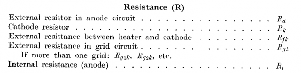
Greetings! Symbols were a great deal less standardised than today, especially across geographic variations. Ketje is using the Philips symbols, which appear in a large amount of literature from Europe (snapshot attached from the Philips technical manual).
Still, even within Philips, this is not held consistently. Mullard was a Philips company, but their 1948 data book defines anode resistance symbols as
ra (inside valve)
Ra (outside valve)
Marconi Osram (1951 data) uses this same standard. But before we can say that British manufacturers were consistent, we find that Brimar used R for loads and Ra for internal anode resistance.
You really have to know in advance what the writer meant by any symbol in historical literature, or at least carefully figure it out.
For drawing new schematics or design-definitions, the small-signal & large signal conventions that Rayma links to are widely used in modern electronics, and are far preferable, IMHO. So Ra, Za, Rp, Zp for external loads (small signal values), and ra (or rp) for internal small-signal resistance are examples of my preferences.
Attachments
Thanks for that. It makes it clear and easy to remember ,
. . . . . though it still bugs me a little that we can't use the notation to learn the principle, we have to already know the principle in order to interpret the notation. I don't like the idea much.
Stick with more recent books and it should be more consistent.
Using lower case for AC and upper case for DC parameters is not as simple as that.
In the formula A = µRa / [ Ri + Ra + ( µ+1 ) Rk ], Ra and Rk doesn't have to be only for DC.
Ra can not only be the actual resistance to + but parallel to it the (capacitor coupled) grid resistor of the next stage, or a transformer or even a CCS.
Same thing for Rk, a LED or a CCS...
Then there also is the possebility of a filter as a load.
More exact would be A = µZa / [ Zi + Za + (µ+1) Zk ], yes also Zi because of anode capacity.
Conclusion, better explane the variables before using them.
Mona
Thanks for that. It makes it clear and easy to remember ,
. . . . . though it still bugs me a little that we can't use the notation to learn the principle, we have to already know the principle in order to interpret the notation. I don't like the idea much.
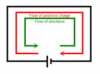
I feel the same about current... In my mind (and in reality), current flows from negative to positive. "Conventional" current should be called "anti-current" IMHO.
Attachments
Last edited:
...it still bugs me a little that we can't use the notation to learn the principle, we have to already know the principle in order to interpret the notation....
Because history. Techs had to fumble with the "principle" before they could do "notation" (to know what to notate).
And as said, there was not universal agreement on notation. Read electronics magazines of old. From the 1930s through the 1960s there were many "recommendations" in the US, and different ones in Europe etc. (The change from mmf thru uuf to pF happened much earlier in much of Europe than in the US.) The IEEE has been working for harmony, but each clique clings to habit, and nobody of universal respect is harmonizing small-tube notation today.
- Status
- This old topic is closed. If you want to reopen this topic, contact a moderator using the "Report Post" button.
- Home
- Amplifiers
- Tubes / Valves
- Glossary