SF, it seems that you are correct about the Johnson noise. I either read that the CC had the worst Johnson noise or maybe I conflated Johnson noise with current noise. I don't get how they can all be the same but I guess I'll have to live with it. Many think that only in very rare instances if at all will the inductance of metal films have an effect on audio frequencies. If there is an oscillation at frequencies much higher than audio I don't know if that would effect the sound or the proper operation of the amp. I assume that people in the know who think it's fine to use MF as stoppers think it is not a sonic of operational issue.
Personally I dont think I can hear it if the grid stop is CC or MF or whatever. I could believe some can in a overdive situation with large ampunts of grid current. Or in class A2 or AB2. I wont, I dont have golden ears. So I just use CC as grid stops from what I believe is a good place to have them. Even in my limited experience I have seen their impressive pulse tolerance. As mentioned earlier by others (tubelab and more) oscillation can occur at 50 and even above 150MHz. Perhaps at those frequencies the reactance of the different types make a difference. I think they do. CCs are about as inductive as their length. Other resistor types have additional inductance due to their construction.
Btw as resistor value goes up the apperant inductance goes down. U need a lot of inductance to dominate a 1Megohm resistor. So resistor parasitic inductance is mostly a concern in lower values.
Is it not part of the purpose of putting the stopper close to the pin to it from acting like an antennae for RF? Here are some "non-inductive" metal film resistors that can take high pulse also. https://www.vishay.com/docs/28729/pr010203.pdf
Is it not part of the purpose of putting the stopper close to the pin to it from acting like an antennae for RF? Here are some "non-inductive" metal film resistors that can take high pulse also. https://www.vishay.com/docs/28729/pr010203.pdf
Yes. Wether the loop resonates at RF and picks up external RF or resonates so it oscillated from the circuits own local excitation doesnt really matter. As close to the pin as possible is the norm.
I cannot see any mention of pulse capability on the datasheet you refered to. ? Just b/c it is a power resistor does not mean it handles transient overload.
Btw a discussion is always fun but we risk dragging this issue into sillyness. Just use whatever gridstop that works. In 99.9% of the times even a 0.5W MF will do just fine. But a CC is a bit safer for supressing HF oscillation for easons mention and do not make any more noise than even the best MF since there is no currents.
Tel: +91-827-559-6123
E-mail: mohit.joshi@vishay.com
New PR02-FS High Pulse, Fusible, Non-Inductive,
Flameproof Metal Film Resistor Offers Defined
Fusing Characteristics
Device Meets the Safety Requirements of UL1412, Features Resistance
> 50 Ω to Handle 600 V Surges
Product Benefits:
• Meets the safety requirements of UL1412
• Defined fusing characteristics
• Resistance values to 100 Ω
• Tolerance down to ± 10 %
• Withstands 600 V surges (1.2/50 µs pulse) as defined by IEC 61000-4-5
• Fast fusing time of < 10 s for an 80 W overload
• Rated power dissipation of 2 W at +70 °C
• RoHS-compliant, halogen-free, and Vishay Green
Market Applications:
• Current limiting in low voltage power supplies for indoor lighting applications
• Electronic home appliances such as washing machines and shaver chargers
• Snu
Tubelab, I'm no electronics expert but I am exploring this subject...… it sure seems likely that an appropriate metal film exists to satisfy the most demanding requirement for a grid stopper
I'm sure that there are plenty. I routinely use the cheap (.01$ each) metal film resistors from Mouser or Digikey in my amp designs with few exceptions.
Two places where I have seen them cause trouble:
The previously mentioned TSE and TSE-II amp designs use a 5842 high GM triode capable of producing high gain well into UHF. It is loaded with a 10M45 CCS chip and followed by a mosfet follower to directly drive a 45, 2A3 or 300B into A2. This is done to provide high stage gain (almost equal to Mu) and eliminate the possibility of blocking distortion. The coupling capacitor between the tube / CCS and the mosfet follower is looking at very high load impedance, so expensive boutique caps are not needed here. The follower drives the grid of the output tube directly through a 100 ohm metal film stopper resistor which is also a fuse in case the mosfet ever fails to a short.
5842's, D3A's and many other high Gm RF tubes will oscillate while still in their original boxes if you look at them funny. Serious layout care and testing is needed when playing with these tubes, especially when connected directly to other high Gm devices like mosfets.
The gate to bias supply resistor on the mosfet follower is 470K or 1 meg, so the 5842 sees the combined load impedance of the CCS chip, the mosfet and its associated gate to bias supply resistor. This is a very high load impedance, around 500K || 5 pF at audio, dropping and becoming non linear with applied audio signal in the mid VHF region.
Yes, I stuck an RF network analyzer at the plate pin and swept the impedance to 3 GHz. I tend to test everything I can in my designs and I was an RF design engineer at Motorola for 41 years. I also have an RF lab in my basement as well as audio and digital work benches, Somewhere I have a Smith chart plot photograph from the network analyzer.
The other area where stopper caution is needed is on the gate of the mosfet follower. Again this is a high impedance node and SOME low value film resistors can provoke bursts of oscillation on signal peaks. I have not seen this in the TSE board, but it can occur in class AB push pull designs at the point where one of the output tubes transitions into or out of cutoff, especially with high Gm TV sweep tubes for output.
I specify a CC resistor for the stopper on the 5842 grid since my builders are scattered all over the world and I can not possible find and test all possible film resistors to determine which ones are "safe" to use. The output tubes get generic 1/4 watt resistors since their GM is low and oscillation is not an issue.
Does this also apply for use as a CF with gain of 1?5842's, D3A's and many other high Gm RF tubes will oscillate while still in their original boxes if you look at them funny. Serious layout care and testing is needed when playing with these tubes, especially when connected directly to other high Gm devices like mosfets.
In theory a gain of greater than 1 is required for oscillation so a follower should not oscillate.
In practice a gain of greater than 1 can be achieved in a follower at RF frequencies since there is always some stray inductance and capacitance associated with each electrode. That plate may be a good audio ground at audio frequencies, but may not be at VHF, so the tube is not truly a follower at RF frequencies.
For most low to medium Gm tubes it's not an issue, but it's possible for a tube originally intended for UHF RF applications to oscillate in unusual ways or places.
I have seen a 6AF4 (rated to 1 GHz) oscillate in a tube tester (readings vary as my hand neared the tube), and some US 6J4's (intended for RF grounded grid up to 500 MHz) oscillate as a follower in a sky wired breadboard.
The previously mentioned mosfet followers were oscillating for brief instants as their loads were transitioning quickly through some point in RF impedance space which along with their internal strays provided some conditions for oscillation in the high VHF region. I have never been able to duplicate these conditions for sustained oscillation with the same fets on the same PC board.
Start with the facts that wiring has inductance, capacitance; and side by side wiring is an air transformer.
Then look at oscillators such as Colpitts, Hartley, Clapp, TPTG, Buttler, etc.
At VHF and UHF, the audio circuits that we build may have wiring, etc. that creates one of the above oscillators.
Grid stoppers kill Q. Low Q can reduce the effects of resonance.
Sometimes the Q killer is a resistor with a wire wound over it in the plate circuit (example, for an 807)
The ARRL Radio Amateur's Handbook can be purchased online.
Better yet, go to the library and look at an earlier version of the handbook, but that was published in the 50s or early 60s.
Check out some of those oscillators.
Then look at some of the VHF and UHF oscillators and amplifiers.
Notice that mere wires are used as coils and transformers.
Compare to how you wired your amplifier.
Last edited:
Does this also apply for use as a CF with gain of 1?
Cathode followers should have a cathode stop resistor, again mounted as close as possible. With their high feedback and often capacitive loads they're always in the danger money territory. A grid stop doesn't hurt anything either.
All good fortune,
Chris
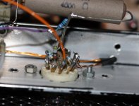
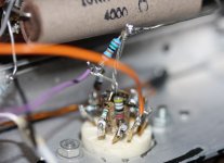
Thanks for the explication guys. I've used the central guide in the noval socket for the four cathode connections on this 6C45Pi. I expected the "HF build style" to be beneficial against HF oscillation, but now I wonder if I'd not better limit the BW of this AF-circuit to f.e. 40KHz with a small cap at the grid.
Attachments
Hi Guys
Nice to see & learn from your in depth discussion, thank you.
Contrary to what was said I replace a 1k 2 watt metal oxide grid stopper resistor on my friends Line Magnetic amplifier with AB resistor, the result was a revelation, timbre etc all became more natural & realistic. Pls don't flame me this is what 3 of us heard after the mod.
Not intended as a flame, what you are describing is an effect; possibly the circuit didn't suffer from oscillation with one resistor type. The differences between types are notable with low value grid stoppers (read above). Exchanging resistor types of the same value never got me far in whatever position I tried. I do not have perfect hearing but my hearing is (was) trained for recording instruments and voices. To some extend I can distinguish the effect H2 has on reproduction but it takes a very low distortion loudspeaker and low listening levels.Hi Guys
Nice to see & learn from your in depth discussion, thank you.
Contrary to what was said I replace a 1k 2 watt metal oxide grid stopper resistor on my friends Line Magnetic amplifier with AB resistor, the result was a revelation, timbre etc all became more natural & realistic. Pls don't flame me this is what 3 of us heard after the mod.
Hi Disco,
Thanks for the reply. When I started this thread I was not prepared to be told that whatever resistor used would not affect sound, reason for my other builds like dac or speaker XO mods, resistors used all affected sound be it in a good way or bad hence. Though I'm not musically trainned I've been expose to life music since young & this has made my hearing in ways very accute to changes.
Cheers
SemperFi, Vishay has a high pulse version of the CMF resistor just for what appears to be a near non existent possibility of blowing out a grid stopper. Those guys at Vishay seem to have an answer for just about everything, except the high price of their metal foils.
CMF Pulse Withstanding Metal Film Resistors, Axial, Industrial, Pulse Withstanding Protective | Vishay
CMF Pulse Withstanding Metal Film Resistors, Axial, Industrial, Pulse Withstanding Protective | Vishay
George, the practice does not contradict the theory.
I never implied that it did. The gain can be greater than 1 in many practical applications due to the stray (unwanted) capacitances associated with EVERY real electrical component. This gets worse with high Gm tubes, especially those intended for use at RF frequencies.
Grid stoppers kill Q. Low Q can reduce the effects of resonance.
Electrical resonance can occur any time an inductance and a capacitance are present in the same circuit. This is just about everything, even a straight piece of wire. The voltage across an inductor or capacitor in a series resonant circuit can be HIGHER than the voltage applied to it. If the inductance in the circuit is a wire, and the capacitance is the electrode of a tube, the apparent voltage gain inside the tube can appear to be greater than 1 at the resonant frequency of the stray components. The input and output voltages in a follower are in phase with other, so oscillation could occur over a wide range of frequencies.
In most "normal" applications the resonances created by wiring and stray capacitance occur at a frequency where the active amplifying device has little gain. This may not be true when tubes designed for VHF or UHF operation or low capacitance mosfets are used.
All of the resonance equations include a "R" term. If R = 0 the voltage across a theoretically perfect capacitor or inductor at resonance is INFINITY, as is the circuit "Q". This is the real reason why simulation software like LT spice doesn't like zero resistance. It forces the computer to divide by zero which confuses it greatly.
As resistance (R) increases the circuit "Q" drops, and so do the voltages in a resonant circuit. Resistance in a resonant circuit must be overcome with gain for a circuit to oscillate. If a complete circuit has enough resistance that the total circuit gain will be less than 1 for ALL operating conditions, then that circuit will not oscillate.....but it may still "ring" if the gain gets near 1 at any frequency.
Ringing is the property of a circuit to start oscillating when an outside stimulus is applied, but the oscillation dies due to insufficient gain.
An inductor can create a huge voltage spike when the current through it abruptly ceases. Tesla made his career out of this property. Driving an amplifier to clipping can cause cutoff in one or both output tubes creating a voltage spike that can be the outside stimulus for initiating ringing. This can occur anywhere in the amp if GNFB is applied, and in the output / driver stages if local feedback is used.
All active devices, especially semiconductors have Voltage Varying Capacitances due to the varying channel width or depletion region. A vacuum tube WILL exhibit the sane VVC effects due to the moving space charge cloud with varying tube current, albeit with a higher (and varying) dynamic impedance. Their capacitance will change with applied signal voltages.
This will cause resonances to move, and circuit "Q" to change with the audio signal, making the prediction of perfect amplifier stability into a reactive load like a speaker with crossover caps rather difficult.
Sometimes the Q killer is a resistor with a wire wound over it in the plate circuit (example, for an 807)
The resistor with wire wound over it was common in RF amps in the vacuum tube era. Often these amps were operated in class C where the tube enters cutoff on every cycle. It is driving a high Q tuned circuit at a HF frequency, but the tube and wiring exhibits stray resonances in the VHF region which will ring. Adding a stopper resistor in the plate circuit will kill this ringing, but waste some HF power. A choke is created in parallel with this resistor to bypass the resistance at HF but create a lossy inductor at VHF to squelch the ringing.
I replace a 1k 2 watt metal oxide grid stopper resistor on my friends..... with AB resistor, the result was a revelation
I can believe this, and have seen examples in my own experiments even if the amp is not continuously oscillating. There could be bursts of ringing present that changed or vanished with different components due to different stray effects.
sumotan, as you likely know the people who say the grid stopper can't or doesn't effect the sound base their opinion on the fact that there is almost no voltage or current on or through the grid stop to create distortion from noise. Too many people like yourself contradict that opinion. I hope to check this out for myself soon. I postulate that there are intangibles involved.
SemperFi, can you please tell me what AC means with respect to the below image? I'll admit I'm new to this subject matter. To me no means no means Zero (0).
https://robrobinette.com/images/Guitar/HowAmpsWork/Triode_Tube_Circuit_with_Signal_Path.jpg
https://robrobinette.com/images/Guitar/HowAmpsWork/Triode_Tube_Circuit_with_Signal_Path.jpg
- Status
- This old topic is closed. If you want to reopen this topic, contact a moderator using the "Report Post" button.
- Home
- Amplifiers
- Tubes / Valves
- Grid stopper resistor question