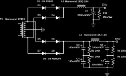
I decided to scrap amp 2 and build it with SS rectification... Layout real estate says I have to mount that cap 2mm from the heater transformer... Hopefully it won't be a hum magnet.
Coils are all Hammond. 278CX for PT, 1650N for OPT, 193Q for reactor, 155J for filtering/smoothing for VA/PI/Driver, and 167V12 for heater supply. Glad I didn't buy them from Digikey. BOM is almost 1000$ CAD for just the coils and chassis parts! If you're in the GTA and want anything Hammond, see Glen at A1 electronic parts... 196 North Queen. index
Any comments?
Attachments
Last edited:
Your 6p36s output valves won't last long with that HT on them.
6P36S, 6P36S-V
6P36S, 6P36S-V
It's using an auto-bias module so it shouldn't be a problem. This data says 1M max, too. 6P36S, 6P36S-V however, most of the data is clearly wrong...
Last edited:
It's using an auto-bias module so it shouldn't be a problem. This data says 1M max, too. 6P36S, 6P36S-V however, most of the data is clearly wrong...
see PDF attachments for extended datasheets of 6p36s (6П36С) !
machine assisted translation of the all russian doc:
6П36С (output beam tetrode) Purpose: work in the output stages of the line scan of television devices of wide application with a beam deflection angle of 110°. Dimensional drawing and wiring diagram of electrodes with external terminals of the lamp 6П36С. 1-grid one; 2-grid one; 3 - the cathode and beam plate 4 - heater; 5 - heater: 6 - grid second; 7-grid two; 8 - cathode and beam plate 9-not connected.
The anode is connected to the upper terminal - cap. Master data Filament voltage 6,3 ± 0,6 In The filament 2 ± 0.15 A The anode voltage nominal (constant) 100 V Anode voltage limit (constant) 250 V Anode voltage limit (constant) cold lamp 550 V Anode voltage limit (pulse amplitude) (note 1) 7 kV Anode current 120 ± 50 mA Anode current (pulse amplitude) (note 2) 400 mA Cathode current limit (average) 250 mA Voltage grid of the first (permanent) Minus 7 V The grid voltage of the first limit (pulse amplitude) (note 3) Minus 250 V Reverse grid current of the first 1 µa The second grid voltage nominal (constant) 100 V
The voltage of the second grid limit (DC) 250 V The voltage of the second grid limit (continuous) cold lamp 550 The grid voltageof the second grid limit (constant) at locked the lamp 330 V The second grid current (pulse amplitude) (note 2) 100 mA Power dissipated by the anode, limit 12 W Power dissipated by the second grid, limit (note 4) 5 W Power dissipated by the anode and the second grid, the limit, total 16 watts
The voltage between the cathode and the heater is the limit 100 V (constant) Slope characteristics 20 ± 6 mA/V Resistance in the first grid circuit, limit (note 5) 0.5 MOhm Capacity input 32 ± 4 pF Capacity output 19 ± 2 pF The feed-through capacitance 1 pF Making - wedge base glass Weight: 90 g
Note 1. When the anode current is not more than 0.1 mA and the pulse duration is not more than 14 µsec ((reverse line scan). The horizontal frequency of about 16 kHz.
Note 2. At anode voltage of 50 V, grid voltage of the second 170 V, voltage the grid of the first, equal to zero, the frequency of the unlocking pulses of the grid the first 50 Hz and 10 duty cycle.
Note 3. The duration and shape of the voltage pulse on the grid should be the first ensure that the lamp is locked during the reverse stroke of the line scan.
Note 4. At the time of turning on the TV (during the heating of the damper diode) power dissipation on the second grid up to 7 watts is allowed.
Note 5. In the diagrams the horizontal allowed the use of a lamp at the resistance in the grid circuit of the first 2.2 MOhm.
Attachments
Last edited:
R38 and R40 are quite high. There's nothing on the datasheet.
2.2 Mohm in TV service
0.5 Mohm otherwise
Sorry looked like fixed bias on the schematic, I guess your measuring the current through the 10R. Wonder how those auto bias things work. You would think that is the signal is very big i.e. in class B then the the non linear current in the tail would confuse the circuit.
Could you go ultra linear?
Could you go ultra linear?
I wouldn't go UL with these tubes, they have a low G2 voltage which isn't an issue in triode since the plate is always slightly more positive.
There is info on how the module works in this thread: Automatic bias board.
There is info on how the module works in this thread: Automatic bias board.
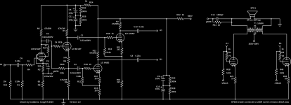
So… KodaBMX, let's see if I get the circuit.
U1A 6F12P pentode: voltage amplifier, inverts signal. Has GNFB injection to cathode. Cool.
U1B 6F12P triode: phase splitter, no gain. Cool.
U2A 6N8S triode: slightly cathode-lifted (wider dynamic range … but enough?) VAS
U3A 12SN triode: Same thing as U2A, but different valve? Hmmm…
U4,5 6P36S triode: Capacitively coupled push-pull output power valves. Cool.
Either the U3A as a 12SN7 is a typo, or it begs why. I'm taking a bet on “typo”.
I was kind of curious as to why the phase splitting outputs are then voltage amplified in the next pair of valve sections. On the one hand “I see it”: whatever nonlinearities of amplifcation of U1A will be modest if the signal is low. Even amplified, a low signal won't have the ability to drive the 6P36S valves on the east side of the 0 dB gain phase reflector.
So, added gain needed. I guess the “feature” is that then using 2 triodes to amplifier each symmetric phase introduces more triode nonlinearity into the signal stream, but now it is complimentary, not just more-to-postive-over-negative signal excursions. If that was the thinking, then I like it.
Finally, one must hope that the output valves' grids never venture in to the positive charge space by much. The prior pair of VAS valves' anode load resistors (hence overall impedance sort of) is fairly high, and actual positive-going signal conduction would add quite a bit of nonlinearity to the output.
Anyway, that's my take.
What transformer doth thou recommend for the PP output? Yet another of the near-magical toroidal power transformers commandeered to the job?
Yours,
GoatGuy ✓
A couple of updates. The amp is now running at 375V B+ for the output stage with each tube fixed biased to 60mA. I blew up a board (make a couple of errors while building including connecting the screens of one tube to the plate of the other. This blew the 220R screen resistors (which I spec as 0.5W film because they blow like a fuse and save the tube) and the cathode resistors on the module.
The VA/PI runs on 530V, the driver 560V.
A curiosity is with the gNFB network. To get 10 kHz square wave to look good, one channel needs 2000pf || 1k, the other only needs 1000pf || 1k.
GoatGuy. I was in the middle of things when I wrote the schematic... 6N8S = 12SN(7) in this case, I forgot to change both of the labels.
I thought a split load phase splitter had a gain of 2? Doesn't matter anyway.
The point of the extra driver is for voltage swing. This VA/PI/Driver should make over 100VRMS from 0.2V input. This allows me to use this circuit for 6P45S triode connrecion (-80V bias roughly)
The output tubes have about -60V bias so the driver needs to be able to swing it for full output which happens before grid is at 0V (The 6P36S will try and move over 1A of triode plate current with the grid still under 10V negative).
It also allows for more gNFB.
I'm using Hammond 1650N for the output, but I'd recommend the dual toroid method. Triad VPT18 with the 4 primaries interleaved in series (to cancel DC core flux) works very well. Not only is there less distortion, there is more power, and less likeliness to "motorboat" with too much gNFB. Also much more robust. An arc won't take out the coil as easily since they are designed for much more current.
I bought all the iron before I discovered toroids and triode connected sweet tubes, and these parts don't really suit anymore so I might sell the lot. Great to make a KT88 amp or the like")
Koda
Here's the current schematics...
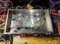
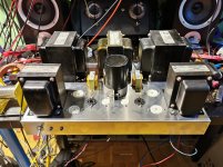
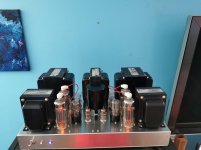
And a photo of it running...
The VA/PI runs on 530V, the driver 560V.
A curiosity is with the gNFB network. To get 10 kHz square wave to look good, one channel needs 2000pf || 1k, the other only needs 1000pf || 1k.
GoatGuy. I was in the middle of things when I wrote the schematic... 6N8S = 12SN(7) in this case, I forgot to change both of the labels.
I thought a split load phase splitter had a gain of 2? Doesn't matter anyway.
The point of the extra driver is for voltage swing. This VA/PI/Driver should make over 100VRMS from 0.2V input. This allows me to use this circuit for 6P45S triode connrecion (-80V bias roughly)
The output tubes have about -60V bias so the driver needs to be able to swing it for full output which happens before grid is at 0V (The 6P36S will try and move over 1A of triode plate current with the grid still under 10V negative).
It also allows for more gNFB.
I'm using Hammond 1650N for the output, but I'd recommend the dual toroid method. Triad VPT18 with the 4 primaries interleaved in series (to cancel DC core flux) works very well. Not only is there less distortion, there is more power, and less likeliness to "motorboat" with too much gNFB. Also much more robust. An arc won't take out the coil as easily since they are designed for much more current.
I bought all the iron before I discovered toroids and triode connected sweet tubes, and these parts don't really suit anymore so I might sell the lot. Great to make a KT88 amp or the like
Koda
Here's the current schematics...
And a photo of it running...
Attachments
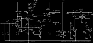
Here's the current schematics…
Thought… maybe R15 and R16 might be better around 4.7 kΩ. A bit more linearity over the whole dynamic range, and less likelihood of having an “internal stage clipping” situation. Won't change the overall gain too too much.
Just saying,
GoatGuy ✓
PS: I see the 12SN7 mislabeling has “gone away!” Bravo, bravo.
You can solve the motor-boating issue by making sure just one of the coupling stages is the dominant pole at LF. In this case reducing the value of C8 and C13 - and making C1, C3 larger - you have add a zero C4 in the NFB which will help with the correct choice of value. Having two poles C8/R40, C3/R11 in the same place is a bad idea. Maybe C8/R40 10Hz, C3/R11 2Hz. The transformer pole is about 3Hz.
For the HF stability it may be worth adding a dominant pole say 12KHz with a zero at the first pole of the transformer about 80KHz. This will bring you loop gain down to a much lower value before you add the zero. You could try series RC across R5 - however if the plate resistance changes with voltage then a non-linearity is created. Don't know - others may give you better advise - I would try the first stage on ltspice.
Sorry C4 is a pole too in the nfb for the LF stability. So you have 4 poles. Nothing you can do about the transformer - so make two poles low in frequency say 2Hz or less and one pole (dominant) say 15Hz to the output stage - this also helps with blocking. Then the dominant pole will bring the fb gain downto 0dB at which point the transformer pole will kick in.
No point having an amp near LF or HF instability.
Hope this helps.
Thanks for the suggestions. The amp is stable as it's built, but if more gNFB was needed, these suggestions would increase stability for sure.
Your suggestions made me realise I made an error in the schematic. R38/R40 are 330k, not 510k, so that pole is different than the first two. Not 15Hz of course, but higher than 1.6Hz...
Your suggestions made me realise I made an error in the schematic. R38/R40 are 330k, not 510k, so that pole is different than the first two. Not 15Hz of course, but higher than 1.6Hz...
- Home
- Amplifiers
- Tubes / Valves
- New build: 6F12P - 6N8S - 6P36S triode push pull.