First
Second, in my “critique of the suggested amplifier”, last night - oh, around 2:30 AM - I got to thinking … and realized that one aspect of my opinion was likely wrong:Tying them to ground, bypassing C₃ entirely is going to result in less feed-in wiggle on U₇. Can't imagine why the designer would want it… just saying.Turns out that since the first stage is not DC decoupled (i.e. no DC blocking capacitor) from the second pair of valves ("the symmetric inverter section"), that the cathode is going to run “up there” voltage wise.
To get a proper bias on the grids still allowing current flow requires some sort of positive bias. I guess the grid-leak approach will do the job.
Just seems a big iffy to me. Iffy from the point of view that as the pair of tubes in the inverter age, it is not obvious that the grid-leak will do what's needed, especially with respect to the 2 tubes as a pair.
GoatGuy ✓
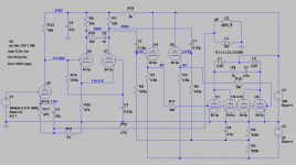
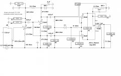
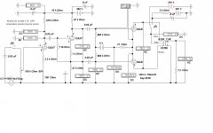
I don't think it is grid leak bias at all ... The plate voltage of the entry stage IS the grid potential of both triodes of the splitter pair. The cathode potential of the pair IS the voltage drop across their common cathode resistor. The effective grid voltage of the pair is the difference between cathode and grid potential. In my case it is a negative 1.66v, not very negative but o.k. Now what happens if the splitter triodes get weaker ? cathode current drops, voltage drop across cathode R drops, cathodes become more negative --> as the grid voltage is unchanged, this means that the grids become more positive, which in turn tends to increase current thru the pair. Works the other way round as well. The whole setup is effectively a DC regulator ... a free servo in a nutshell ... Similarly, should the input triode get weaker, its plate voltage rises, grid voltage of the pair rises, current rises, voltage drop across their cathode R rises, cathodes go up, effectively making their grids more negative, compensating the rise in grid potential, the usual working of a cathode Rs negative FB ... Have a look at the attached schematic, it now shows the actual voltages.
Attachments
I don't think it is grid leak bias at all ...
The plate voltage of the entry stage IS the grid potential of both triodes of the splitter pair.
...
Have a look at the attached schematic, it now shows the actual voltages.
Right you are.
As I said … 2:30 in the morning, is not a good time to trust one's analytics! Thanks. GoatGuy ✓
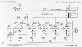
How does 15 mA at 210V on the plates of the PCC88 translate into 2.5 Watts of audio?That implies 79% efficiency, not too likely. Did I miss something?Practical Wireless published a power amplifier design based on ECC83 + PCC88. The author declares 2.5W at 1% distortion (1 KHz) with 10 ohm load. That's not bad at all. The design also featured a unconventional preamp section depicted in the bottom half of the schematic.
At no signal the 2.5W total plate input exceeds the 2W total rating shew on some data sheets.

Look at the power supply: there's a series resistor from 287V to the transformer's center tap. That resistor has to be calculated for maximum anode current of the AB1 stage so without signal the anode voltage is higher and a short burst of music might deliver 2.5W. A better alternative would have been to omit the series resistor and to use an output transformer with higher Raa. Also lowering the quiescent current to keep dissipation within proper limits, temporarily exceeding it only at signal peaks just like is done for transmitting tubes (rated for CCS and ICAS).
How does 15 mA at 210V on the plates of the PCC88 translate into 2.5 Watts of audio?That implies 79% efficiency, not too likely. Did I miss something?
At no signal the 2.5W total plate input exceeds the 2W total rating shew on some data sheets.
who says they stay in class A ? your efficiency calculation is mute in class B.
theoretically you could bias a pure class B pp output to zero mA plate current and still get 2.5W out; the way you calculate efficiency this would translate into infinite efficiency; but that's not how efficiency is calculated in class B which is (power out to speaker) / (power in from PS). also note that in class B dissipated power (aka heat) is small w/o signal - max happens at around 40% output and drops slightly towards full output.
also, they use ECC88 which has a 1.8W allowance "chaque system" say all the ECC88 data sheets, the 6n23p too, so 3.6W per bottle.
and yes, they violate the max plate volt limit for ECC88 which is set at 130v. however the ECC88 was developed for cascode service in TV sets where the max PS was 260v for 2 triodes in series. setting the limit to 130 was no restriction for that purpose and also avoided any discussion about elevating the heater bias for the upper triode in the stack which was in the same bottle.
In reality the ECC88 can easily cope with 250v.
What It Takes to get 3W Continuous
In the HIFI wars of the 60s & 70s there was quite a debate on how to rate audio power output. Many of the claims of output power were ridiculous, this is simply another of that era. Class AB1 invites serious clipping & blocking, something Crowhurst warned about in many of his pieces. I did look at the resistor in series with the PS, very large for that place I thought. Why not start with the proper supply in the first place, sagging supply is not great for the output stage. What does it do to a series of transients. I've looked at that as well on another amp built to study that. In a Class AB2 amp.
How does one measure the D% at that implied 2.5W output. Need to agree how these measurements are made so that accurate comparisons of various systems can be compared at a distance. Good science & engineering dictates that. Looks like the author of that article never made any measurements of real power, perhaps simply drove the amp hard without looking at the waveform.
Someone needs to do a quick build, check his work, see what happens.
The ECC88/6DJ8 family has a very short grid base as we would expect given a mu of 33. It was never meant as an audio tube but serves well at VHF as a grounded grid amp of convertor. The total plate dissipation is very limited, that does set a max whether Class A or AB1. It might do one Watt in Class A on a good day, after losses in the OPT
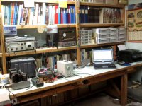
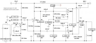
Here is one I did early this year, it is still here in hardware on the bench. It does an honest 3W continuous at low D without NFB. At no signal or 3W it dissipates 12.4W, a little above the rating of the 6BX7 with no signal. All of the parts are low cost, right off the shelf. No boutique BS at all. The 6BX7 pinout is the same as 6SN7, 6BL7 & 5998. So I ran a series of tests on all. The distortion plots are run on a Pico Tech 3224. The power measurements measured with a Gossen MetraHit 29S Precision DVM & Wattmeter. The schematic was done on Electronic Workbench v5.
I have confidence in these results, but not at all for the PCC88 amp.
In the HIFI wars of the 60s & 70s there was quite a debate on how to rate audio power output. Many of the claims of output power were ridiculous, this is simply another of that era. Class AB1 invites serious clipping & blocking, something Crowhurst warned about in many of his pieces. I did look at the resistor in series with the PS, very large for that place I thought. Why not start with the proper supply in the first place, sagging supply is not great for the output stage. What does it do to a series of transients. I've looked at that as well on another amp built to study that. In a Class AB2 amp.
How does one measure the D% at that implied 2.5W output. Need to agree how these measurements are made so that accurate comparisons of various systems can be compared at a distance. Good science & engineering dictates that. Looks like the author of that article never made any measurements of real power, perhaps simply drove the amp hard without looking at the waveform.
Someone needs to do a quick build, check his work, see what happens.
The ECC88/6DJ8 family has a very short grid base as we would expect given a mu of 33. It was never meant as an audio tube but serves well at VHF as a grounded grid amp of convertor. The total plate dissipation is very limited, that does set a max whether Class A or AB1. It might do one Watt in Class A on a good day, after losses in the OPT
Here is one I did early this year, it is still here in hardware on the bench. It does an honest 3W continuous at low D without NFB. At no signal or 3W it dissipates 12.4W, a little above the rating of the 6BX7 with no signal. All of the parts are low cost, right off the shelf. No boutique BS at all.
The 6BX7 pinout is the same as 6SN7, 6BL7 & 5998. So I ran a series of tests on all. The distortion plots are run on a Pico Tech 3224. The power measurements measured with a Gossen MetraHit 29S Precision DVM & Wattmeter. The schematic was done on Electronic Workbench v5. I have confidence in these results, but not at all for the PCC88 amp.
Attachments
-
6BX7GT GE.pdf328 KB · Views: 45
-
 IMG_3993 Betty Crocker Special 10C 16 W FL.jpg391.7 KB · Views: 136
 -
 PP 6BX7 Amp 6SL7 Driver w 5998 Bias Detail.JPG85.9 KB · Views: 149
 -
 2019_03_04_001 PP 6BX7 One Watt.jpg132.8 KB · Views: 147
 -
 2019_03_04_001 PP 6BX7 2 Watts 6SL7 Split Load Inverter.jpg139 KB · Views: 125
 -
 2019_03_04_001 PP 6BX7 3 Watts 6SL7 Split Load Inverter.jpg145 KB · Views: 40
 -
29S B.pdf244.1 KB · Views: 41
Small 9-Pin Toobz Running Class B
These where used as modulators in some small 50s transmitters. Drive an 807 or 6146. But I thought DIY was quality sound, not the public address kind. Maybe not!
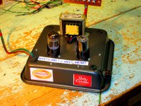
And the Betty Crocker Special running a PP 6BL7. Saw this technique in the Joe Roberts audio magazine, Sound Practices about 20 yrs ago, build in a cooking utensil. I wouldn't build an amp for testing this way again, need to get at the connexions inside too often for performance measurements.
These where used as modulators in some small 50s transmitters. Drive an 807 or 6146. But I thought DIY was quality sound, not the public address kind. Maybe not!
And the Betty Crocker Special running a PP 6BL7. Saw this technique in the Joe Roberts audio magazine, Sound Practices about 20 yrs ago, build in a cooking utensil. I wouldn't build an amp for testing this way again, need to get at the connexions inside too often for performance measurements.
Attachments
I have a guitar amp with SE ECC82 output, the power is ca 1 W, but the intention was to get some distortion from it. Inspired by the Hughes and Kettner Cream machine, it was a success. Such a tiny power amp would work e.g. with Lowther FR speakers or mid/hig compression drivers. I was actually considering building one (ECC82 SE stereo) before I got my hands on a cheap EL84 SE DIY amp and another FU32 based Chinese amp with SMPS. A simple and small 1W tube amp is I think a nice to have thing.
6DJ8_12AX7 PP Amplifier
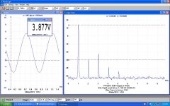
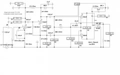
First pass shews barely a Watt into the load & grid current would flow. The top trace is the output to the load, the other trace is the voltage at the 6DJ8 grids. Plenty of gain for use with NFB. This should stir things up a bit! More tomorrow.
First pass shews barely a Watt into the load & grid current would flow. The top trace is the output to the load, the other trace is the voltage at the 6DJ8 grids. Plenty of gain for use with NFB. This should stir things up a bit! More tomorrow.
Attachments
So, after having had a few days to digest the whole situation, I think I need to explore a sidetrack to my initial thought. Since my rig is silent, I need to focus on dirt simple projects. Since I haven't been doing electronics for a few years, all of my equipment is either gone or in storage, another reason for simplicity. Just trying to keep it real here... Budget is also a limiting factor, not necessarily a deal breaker, but non the less limiting.
So, what is the easiest route one can take? It doesn't get much simpler than a SPUD, right? And... 1. How about using a step-up transformer on the input (is this what they call inter stage transformer)? I do live in Lundahl country after all. That will allow you to easily hook up both single ended and balanced sources. If you're going for a truly balanced source with standard pro-level signals and stick with a differential topology, this should help getting the amplitude up... 2. At this point a basic spud 101 isn't going to be quite enough I suspect. Let's explore a SPPUD... The differential topology pretty much seals the deal, it'll have to be Push/Pull. 3. Finish it off with the usual output transformer.
Is this realistic? Is this doable? How much power can you squeeze out of this kind of circuit? What tubes would be a good match? What transformers are suitable?
My speakers are roughly 6 ohm, 95db efficiency, and I've been running a 10db Linkwitz transform to extend the bottom. (Two-way speakers, x-over @ 1300'ish Hz, 15" mid range as bottom.) Without the Linkwits transform, I could probably have gotten by with one or a couple of Watts. With the transform... Let's assume I dial it back a little and aim for 9db, that'll increase the power requirements by x8'ish (I hope I'm remembering this correctly). So, a realistic goal should be an amp that'll give me 10-15 real usable watts. That should get me in the ball park and in worst case I could dial the Linkwitz transform down another notch.
Is that doable? A 15W SPPUD? To keep things in line with the KISS concept, exotic tubes made out of unobtanium are out. Standard transformers would be nice, but if I really have to I might be persuaded to look into having some custom made (in the end it would come down to exactly how expensive the custom option would be).
With only one pair of tubes per channel, the power supply should be manageable and the amps won't substitute my radiators in the winter time. Am I delusional or could this be a winning concept?
So, what is the easiest route one can take? It doesn't get much simpler than a SPUD, right? And... 1. How about using a step-up transformer on the input (is this what they call inter stage transformer)? I do live in Lundahl country after all.
That will allow you to easily hook up both single ended and balanced sources. If you're going for a truly balanced source with standard pro-level signals and stick with a differential topology, this should help getting the amplitude up... 2. At this point a basic spud 101 isn't going to be quite enough I suspect. Let's explore a SPPUD... The differential topology pretty much seals the deal, it'll have to be Push/Pull. 3. Finish it off with the usual output transformer.Is this realistic? Is this doable? How much power can you squeeze out of this kind of circuit? What tubes would be a good match? What transformers are suitable?
My speakers are roughly 6 ohm, 95db efficiency, and I've been running a 10db Linkwitz transform to extend the bottom. (Two-way speakers, x-over @ 1300'ish Hz, 15" mid range as bottom.) Without the Linkwits transform, I could probably have gotten by with one or a couple of Watts. With the transform... Let's assume I dial it back a little and aim for 9db, that'll increase the power requirements by x8'ish (I hope I'm remembering this correctly). So, a realistic goal should be an amp that'll give me 10-15 real usable watts. That should get me in the ball park and in worst case I could dial the Linkwitz transform down another notch.
Is that doable? A 15W SPPUD? To keep things in line with the KISS concept, exotic tubes made out of unobtanium are out. Standard transformers would be nice, but if I really have to I might be persuaded to look into having some custom made (in the end it would come down to exactly how expensive the custom option would be).
With only one pair of tubes per channel, the power supply should be manageable and the amps won't substitute my radiators in the winter time. Am I delusional or could this be a winning concept?
A couple of days ago I had one of my mono-blocks go silent on me, and although I am trying to bring it back to life, it did get me thinking. What do I do if it’s dead?
I have ridiculously sensitive speakers and a box full of old Russian equivalents of ECC88 tubes. Could you build a power amp from these tubes? I know they are commonly used is pre-amps, but could you do it and get some good results? I think my speakers have a 95db sensitivity (6 ohm), so you could probably get away with pretty low power.
My current amps are beasts and I use the power to extend the base with DSP, but I’m sure I could manage with much less.
Dissipation and Va (maximum) is too low , Look into triode connected 6E5P for a simple amp for HE speakers
cheers
316a
Simulation B 6DJ8 PP Amp
The first simulation used the author’s component values. For this simulation I-
1) Removed the three cathode caps. This amp has more than enough gain even without them. Fewer LF steps are an advantage while working with NFB circuits. Bu this one is OK, since triodes are in the output, the output stage gain can never be more than a few db above that with a normal load. Not so with pentodes.
2) Reset the P-P 6DJ8 load to 5.25K, hoping that would result in somewhat more audio power. That got 0.91W at clipping. Looks like the 2.5W claimed is a long way off.
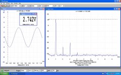
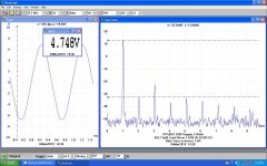
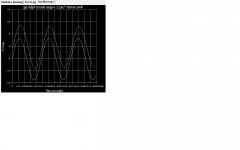
Since the cathode cap was removed from the 6DJ8 cathodes it was possible to look directly at the cathode current. At this audio level it appears the peak current measures ~65 mA. A larger drive signal would result in grid current, thus biasing the grids in the negative direction. The result is blocking of the signal.
The red scope trace follows the cathodes, the black trace is the voltage across the load resister. The PS can be improved by using a full bridge rectifier. Regulation improves, ripple easier to filter. The half-wave rectifier does not make good use of the PT, the Utilization Factor (PF) is very low. And also results in DC biasing of the PT core. Silicon rectifiers & packaged bridges were available at a good price when (1964) this amp was built. I still have some in my stash from work in the lab.
The first simulation used the author’s component values. For this simulation I-
1) Removed the three cathode caps. This amp has more than enough gain even without them. Fewer LF steps are an advantage while working with NFB circuits. Bu this one is OK, since triodes are in the output, the output stage gain can never be more than a few db above that with a normal load. Not so with pentodes.
2) Reset the P-P 6DJ8 load to 5.25K, hoping that would result in somewhat more audio power. That got 0.91W at clipping. Looks like the 2.5W claimed is a long way off.
Since the cathode cap was removed from the 6DJ8 cathodes it was possible to look directly at the cathode current. At this audio level it appears the peak current measures ~65 mA. A larger drive signal would result in grid current, thus biasing the grids in the negative direction. The result is blocking of the signal.
The red scope trace follows the cathodes, the black trace is the voltage across the load resister. The PS can be improved by using a full bridge rectifier. Regulation improves, ripple easier to filter. The half-wave rectifier does not make good use of the PT, the Utilization Factor (PF) is very low. And also results in DC biasing of the PT core. Silicon rectifiers & packaged bridges were available at a good price when (1964) this amp was built. I still have some in my stash from work in the lab.
Attachments
Simulation C 6DJ8 PP Amp
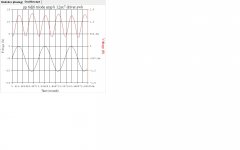
For this sim a PS of 210V was switched in. That way power available for a single large signal could be measured. Simulations are good for a couple of reasons, there is no smoke resulting from a connexion error. And toobz don’t cook operating in overload conditions. The result here is 1.63 Watts, getting closer to what the author of the 6DJ8 PP Amp article claims. So looks like 0.91 Watts if the signal is a continuous sine wave & 1.63 Watts max at well spaced intervals.
I’ve done this in hardware about 20 yrs ago on a PP 6V6 amp running Class AB2 with an intended, limited PS. The amp was 17W continuous on the self contained PS, 26W on a regulated PS.
Attachments
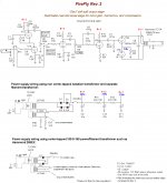
Doug Hammonds Firefly
This small amp was designed by Doug Hammond of Hammond Mfg. So all Hammond iron.I have a guitar amp with SE ECC82 output, the power is ca 1 W, but the intention was to get some distortion from it. Inspired by the Hughes and Kettner Cream machine, it was a success. Such a tiny power amp would work e.g. with Lowther FR speakers or mid/hig compression drivers. I was actually considering building one (ECC82 SE stereo) before I got my hands on a cheap EL84 SE DIY amp and another FU32 based Chinese amp with SMPS. A simple and small 1W tube amp is I think a nice to have thing.
Attachments
Hi Markus,
attached you´ll find a paralleled single ended circuit from Mr Klaus Böhm, Cologne, Germany, which was published about 17 years ago. His website with additional building instructions vanished a long time ago.
Regards, Tom
attached you´ll find a paralleled single ended circuit from Mr Klaus Böhm, Cologne, Germany, which was published about 17 years ago. His website with additional building instructions vanished a long time ago.
Regards, Tom
Attachments
- Status
- This old topic is closed. If you want to reopen this topic, contact a moderator using the "Report Post" button.
- Home
- Amplifiers
- Tubes / Valves
- ECC88 for power amp?