I was going to say what Osvaldo just added: there's 5.67W in heater, and maybe 2W in screen.
35+5.67+2W= 42.67 Watts full-hot 6L6GC
My IR thermometer work on a 6550 @ 39W Pdiss clearly showed max observed temperature "around" the plate and significantly lower temp at top and bottom.
A non-calibrated observation: I once burned my hand on a coke-bottle 6550. The 1st-degree burn was coke-bottle shape and worst around the plate area.
Tempilstik Temperature Indicating Sticks are the time-honored way to measure surface temperature without adding much thermal mass or insulation. Sadly each only indicates one temperature and they are not cheap enough for a DIY-er to have a "full set".
Tempilstik – markal.com
Fastenal link
Last edited:
If you have access to physically small thermocouples, and were keen enough, you could set up some jigs to see how much variation you get with each jig, and using the normal techniques like keeping the thermocouple wire on the glass for some distance to avoid thermal wicking.
That could be backed up by using thermal colour change patches, and by using the cheap thermal guns (again set up in a jig to maintain pointing and distance, and knowing the sensor's response).
All good fun if that is what you are interested in.
A practical output is to keep the glass clean, and heed the advise on anode orientation when locating valves beside each other (or others, as some quads and sextets can look decidedly cramped together and close to nearby vertical surfaces like transformer windings).
from "Kohl 1960 Materials and Techniques for Electron Tubes"
This is sooo cool! Brilliant find, thank you!
In the computations below, I believe you forgot to consider heater and screen dissipation, all of them constitutes part of the heat radiated from the envelope. Note that some tubes (In my design 6JN6's) runs very hot with the heater only powered.
You are quite correct, I have indeed neglected that.
Let me do over: to stay with the same tube, a 6L6GC heater dissipates 5W and the heater roughly 6W, so we're looking at 41W at full power or maybe 27W at 40mA, which give respectively 212C (24W radiation and 17W convection) and 157C (15W/12W) average envelope temperature.
My IR thermometer work on a 6550 @ 39W Pdiss clearly showed max observed temperature "around" the plate and significantly lower temp at top and bottom.
A non-calibrated observation: I once burned my hand on a coke-bottle 6550. The 1st-degree burn was coke-bottle shape and worst around the plate area.
Yes, this is my memory of the reading from the FLIR as well. So much that I casually thought I was seeing through the glass (at the time I wasn't aware the IR absorption would be so pronounced). I have in the meantime gathered a few dustbin-grade tubes, I intend to cut the envelope open and run a few experiments over the weekend, I'll post some picture as soon as I have any.
If you have access to physically small thermocouples, and were keen enough, you could set up some jigs to see how much variation you get with each jig, and using the normal techniques like keeping the thermocouple wire on the glass for some distance to avoid thermal wicking.
That could be backed up by using thermal colour change patches, and by using the cheap thermal guns (again set up in a jig to maintain pointing and distance, and knowing the sensor's response).
All good fun if that is what you are interested in.
Well this is the power of the white rabbit, isn't it...
") (I do deal with radiative transport at work, so I have some affinity with this problem space)
(I do deal with radiative transport at work, so I have some affinity with this problem space)I was wondering more on the side of what PRR was saying, to use a "sock" of thin diffuse material (piece of black cloth or paper?) fitting snugly the envelope to improve the reading ability of the IR thermometer.
A practical output is to keep the glass clean, and heed the advice on anode orientation when locating valves beside each other (or others, as some quads and sextets can look decidedly cramped together and close to nearby vertical surfaces like transformer windings).
Reading this made me think if we couldn't actually visualize the radiation spread of the tube, maybe heat it up and disperse some dust in the air (flour?) then quickly take a picture. Trying to create a form of Tyndall effect, you know, like this
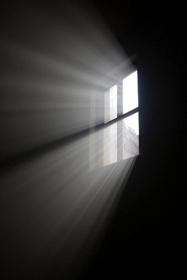
A quick look on the web seems to indicate acrylic could be a way to do this. Possibly there is enough irregularity in the material that holding it horizontally (you know, "edge on") next to the tube might reveal a cross section of the radiated field, like this:

Think they get much hotter than 160 deg. The glass may stop your camera reading the correct result. If they glow a dull red then its about 500 degC, so maybe 400 degC.
That's right. If the plate is running at 30W, plus 5ish screen plus 6ish heater, you're looking at 41W of radiation, which should be approximately 485C at the plate (and 212C at the envelope), both average temperatures, and both assuming my estimations of the sizes are accurate enough.
Let me do over: to stay with the same tube, a 6L6GC heater dissipates 5W and the heater roughly 6W, ...
Bah. 5W *screen* of course, 6ish W heater. Or the more accurate numbers from PRR
> approximately 485C at the plate (and 212C at the envelope)
These are roughly as described in the J. P. Welch essay cited above. 500C in plate, and we would "like" <175C on glass for longevity, but a 6L6GC's work suggests compromise. I don't know the number for 6L6GC, but Tung-Sol (who knew hot glass seals) made 5881 to replace 6L6 in applications where 6L6 was not lasting; and made 6550 for bigger chores; 6550 is rated 250C on glass (and seems to be OK with that). I happened on a lesser tube rated 165C glass (a tight spec 6SN7 so probably conservative for low drift).
> 5W *screen* of course
In _6L6(GC)_ screen current is typically quite small, 5%-7% of plate current. Simplifying, we dart-toss 2W-3W, rarely 5W (except in severe overdrive). (Ah, but 6L6GC has a twin with a top-cap, for TV H-sweep duty, and there screen dissipation may be quite high.)
Last edited:
In _6L6(GC)_ screen current is typically quite small, 5%-7% of plate current.
Yes, in my circuit there seems to be approx 2mA flowing through the screen, which at 450V approx would make just about 0.9W dissipation.
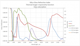
I've read a few papers, and put together the plot attached:
- left axis is for Index of Refraction (complex: real part in red, imaginary in blue)
- right axis is for the rest
- green is the relative response of the FLIR i7
- purple, light blue and orange are the transmittance of the glass at thicknesses of 50, 250 and 750 um, where 750um is approximately our thickness.
The data is from this paper:
R. Kitamura, L. Pilon, and M. Jonasz, 2007. Optical Constants of Fused Quartz From Extreme Ultraviolet to Far Infrared at Near Room Temperatures. Applied Optics, Vol. 46, No. 33, pp. 8118-8133.
The absorption curves come from the imaginary part of the index of refraction: it's also called the extinction coefficient, and it's related to transmittance as
T = exp(-2\pi k x / \lambda_0)
where k is the extinction coefficient and \lambda_0 is the wavelength in vacuum and x is the distance traveled.
This Stack Exchange answer has a very nice derivation of the relation above from John Rennie.
Lastly I observe the very complex shape of the real part of the IOR, goin from 0.35 to 2.5 in one micron and then staying mostly above 2 in the region where the instrument has an sensitivity.
The next step I have in mind is to plot the emission resulting from this and its angular dependence, looks like it'll be quite shapey
Attachments
Last edited:
Or perhaps it shows that the FLIR CCD is ineffective at measuring the plate through the glass envelope, regardless of any sort of attempt to 'mis calibrate' the device to in an attempt to overcome the short coming of the device and read the temperature better.
I'm sure I read somewhere that the temperature can be approximated by the perceived colour, and if ball park is good enough, then +/- 25 degrees may be good enough, and feasible?
Other than cracking a tube opens and then putting the FLIR and tube electrodes into a new vacuum....
But then, that much effort, or this much effort? What does it actually achieve?
Say it's about 450 degrees at full barely visible red. I'm not sure what any more accuracy gets you.
Surely it's now more of a semantic study.
The anode is then either, hot enough, or too hot.
Last edited:
Other than cracking a tube opens and then putting the FLIR and tube electrodes into a new vacuum....
at that point I would just spot-weld a thermocouple to whatever you want to analyze
Or perhaps it shows that the FLIR CCD is ineffective at measuring the plate through the glass envelope, regardless of any sort of attempt to 'mis calibrate' the device to in an attempt to overcome the short coming of the device and read the temperature better.
My point was more that the FLIR misestimates the temperature of the glass, because really it's the spectral distribution of the glass radiated field that violates the assumptions built in the thermal imager.
I've been a bit quiet here because I'm reading some papers from the 1950's about how this stuff is measured, this person named Gardon has published a fair bit on the subject. I'm intending to come back with further information once I get some closure, likely in a few days.
I like cliff-hangers, but my clock says it's 2021My point was more that the FLIR misestimates the temperature of the glass, because really it's the spectral distribution of the glass radiated field that violates the assumptions built in the thermal imager.
I've been a bit quiet here because I'm reading some papers from the 1950's about how this stuff is measured, this person named Gardon has published a fair bit on the subject. I'm intending to come back with further information once I get some closure, likely in a few days.
Are you back from the 50's yet, or should we call Doc and stick some plutonium in the DeLorean? Just to catch up, the surface temp of a 6L6 is getting into what temperature range? like 200° C or so? But inside the tube plate gets to 400-500° C or so? So pointing an IR thermometer and reading will give internal plate or external glass reading? What's a good way to get only external glass temp? Putting a bimetal thermometer next to or on top of the tube with some wire?
Thanks
- Status
- This old topic is closed. If you want to reopen this topic, contact a moderator using the "Report Post" button.
- Home
- Amplifiers
- Tubes / Valves
- Plate temperature measurement