Hi all,
I will start admitting I may have been following a white rabbit passing by a little too far. Maybe. However:
I have recently restored/rebuilt a tube amplifier (it happens to be a guitar amp, but you'll see in a moment that won't make much difference to this question) and as I was checking it was all rebuilt well, I set up the bias levels and took a quick look at temperatures of various components all around the amp. This I've done relatively casually using a FLIR i7 thermal imaging camera (a very fun device). I'm a bit fretty because I used a heater wiring that has insulation in PVC and I was concerned it might have heat trouble.
As I was looking around things, I noticed that the plates of the output tubes (a quad of 6L6GC's) read as having a hot spot of approx 160C near the center. The idle current is 40mA and the center tap of the output transformer is 450V, so that the plate is dissipating 18W at idle.
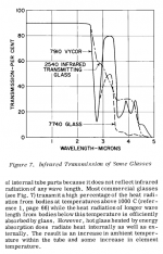
Now the question: if I understand correctly, the only way the plate has to dissipate 18W is to radiate heat away, because the vacuum impedes convective flow, and the pins will do some conduction, but not enough to worry about it.
Indeed the FLIR says the pins on the socket are at approximately 37C, some 15-20C above ambient, but not much heat flow there.
However, applying Stefan-Boltzmann's law to the plate body, it seems you get a dissipation rate of about 5.5W, which really makes no sense to me.
Here's my reasoning:
- heat dissipated is \sigma T^4 [W/m^2]
- \sigma ~= .85 (which I think is high as an estimate, because the plates are dark, but far from black, and eyeballing them they don't look very rough)
- T = 160C = 440.15K implies we get 2128W/m^2
- the area of the plate on a 6L6GC is approx 32cm^2: it's 32mm tall, and seems to be approx 50mm wide if you sum the width of the front, side and "stitching" surfaces, then double for front and back
- the glass will absorb some IR for sure. On the one side you'd think the manufacturer goes out of their way to minimize this effect, on the other maybe they're just using moderately priced glass after all. The expectation is that the envelope will then do a combination of radiation (small, it's very shiny, and shiny things have low \sigma's) and convection through air
Some fine print:
- when computing the plate area you only need the external facing surface of the plate, but not the inner one. That one radiates onto the inner side of the plate opposite from it, which then absorbs it.
- Whatever reflection is left from said inner surface goes back to the emitter and so on. This is like a radiation furnace. There will be some heat escaping top and bottom, of course, but I doubt that'll be more than say 20% (the micas tend to be lightly coloured, and seem to stay much colder judging from the FLIR's reading)
- Note that using the full area as if it was all at peak temperature is also an over estimation: there is no way the "stitching" sides are anywhere near this hot, and even the plate "proper" has a clear temperature gradient across it, about the shape you'd have in a red-plating tube. This is expected because it's where most of the electrons actually hit it, and I'll bet a major component of the gradient is actually heat conduction in the metal
- about the glass: the emission spectrum can be plotted here: at 311C the peak is at 5um, at 170C it's maybe closer to 6.5um. Judgin from this plot, around 5-6um the absorption is just under 5% per mm thickness (maybe 4%?). I haven't checked but I doubt a 6L6 has an envelope thicker than 1 mm
It seems that to radiate away 18W you'd need a plate that is at an *average* temperature of 311C (likely more, because as I said, I don't believe the \sigma estimate is low enough).
Can anybody explain this? I really feel like I'm missing something obvious here.
Thanks for whatever insight you might share
I will start admitting I may have been following a white rabbit passing by a little too far. Maybe. However:
I have recently restored/rebuilt a tube amplifier (it happens to be a guitar amp, but you'll see in a moment that won't make much difference to this question) and as I was checking it was all rebuilt well, I set up the bias levels and took a quick look at temperatures of various components all around the amp. This I've done relatively casually using a FLIR i7 thermal imaging camera (a very fun device). I'm a bit fretty because I used a heater wiring that has insulation in PVC and I was concerned it might have heat trouble.
As I was looking around things, I noticed that the plates of the output tubes (a quad of 6L6GC's) read as having a hot spot of approx 160C near the center. The idle current is 40mA and the center tap of the output transformer is 450V, so that the plate is dissipating 18W at idle.
Now the question: if I understand correctly, the only way the plate has to dissipate 18W is to radiate heat away, because the vacuum impedes convective flow, and the pins will do some conduction, but not enough to worry about it.
Indeed the FLIR says the pins on the socket are at approximately 37C, some 15-20C above ambient, but not much heat flow there.
However, applying Stefan-Boltzmann's law to the plate body, it seems you get a dissipation rate of about 5.5W, which really makes no sense to me.
Here's my reasoning:
- heat dissipated is \sigma T^4 [W/m^2]
- \sigma ~= .85 (which I think is high as an estimate, because the plates are dark, but far from black, and eyeballing them they don't look very rough)
- T = 160C = 440.15K implies we get 2128W/m^2
- the area of the plate on a 6L6GC is approx 32cm^2: it's 32mm tall, and seems to be approx 50mm wide if you sum the width of the front, side and "stitching" surfaces, then double for front and back
- the glass will absorb some IR for sure. On the one side you'd think the manufacturer goes out of their way to minimize this effect, on the other maybe they're just using moderately priced glass after all. The expectation is that the envelope will then do a combination of radiation (small, it's very shiny, and shiny things have low \sigma's) and convection through air
Some fine print:
- when computing the plate area you only need the external facing surface of the plate, but not the inner one. That one radiates onto the inner side of the plate opposite from it, which then absorbs it.
- Whatever reflection is left from said inner surface goes back to the emitter and so on. This is like a radiation furnace. There will be some heat escaping top and bottom, of course, but I doubt that'll be more than say 20% (the micas tend to be lightly coloured, and seem to stay much colder judging from the FLIR's reading)
- Note that using the full area as if it was all at peak temperature is also an over estimation: there is no way the "stitching" sides are anywhere near this hot, and even the plate "proper" has a clear temperature gradient across it, about the shape you'd have in a red-plating tube. This is expected because it's where most of the electrons actually hit it, and I'll bet a major component of the gradient is actually heat conduction in the metal
- about the glass: the emission spectrum can be plotted here: at 311C the peak is at 5um, at 170C it's maybe closer to 6.5um. Judgin from this plot, around 5-6um the absorption is just under 5% per mm thickness (maybe 4%?). I haven't checked but I doubt a 6L6 has an envelope thicker than 1 mm
It seems that to radiate away 18W you'd need a plate that is at an *average* temperature of 311C (likely more, because as I said, I don't believe the \sigma estimate is low enough).
Can anybody explain this? I really feel like I'm missing something obvious here.
Thanks for whatever insight you might share
Can´t "explain" anything, specially because I would need more data, but:
In principle,having just a hot spot reaching mere 160C and it being just a small fraction of total area, makes me think 2 things:
* your meter o measuring technique has some error, period.
* or tube is dissipating less than you think
plus one factor which might explain significative differences:
I think you assume IR leaving plate surface at a 90 degrees angle ... in which case it would irradiate in a cylindrical shape, same height as the plate "cylinder" , while I guess each surface point irradiates in a diffuse omnidirectional way.
What´s my point?
If IR were visible light instead , you woukd be able to see a glowing plate structure anywhere you look from, solid 360 degrees around, ... just not uniform intensity depending on "visible surface" from observer´s point of view.
Meaning an important part of IR radiation is escaping all over the place and not just towards IR meter lens or window.
> the area of the plate on a 6L6GC
For our purposes, heat comes off a tube by *convection* from the *glass*. {edited from "convention"}
Soft glass can't run hot enough for radiation to be significant.
Power-tube glass is often rated 250 deg C max envelope temperature.
Yes, heat flows from plate to glass mostly by radiation. My experience is that a FLIR can't see through glass, but reads the glass temp (and often incorrectly unless you paste some paper on it).
Last edited:
In principle,having just a hot spot reaching mere 160C and it being just a small fraction of total area, makes me think 2 things:
* your meter or measuring technique has some error, period.
Possibly, although I'm not so sure how that would happen (see below). In other words: clearly there is some error, the question is where, what error, and why
")
* or tube is dissipating less than you think
Well yes. This is a fair point to make. So here's my setup: I'm measuring voltage drop across the OT windings to measure current and voltage to ground from the center tap to measure plate voltage. Then I'm using the difference of the two for actual plate voltage, and the voltage across the winding divided by the cold resistance to measure current.
I own two Fluke 8840a meters (5.5 digits, calibrated a couple years back, admittedly), but for this particula setup I used a couple 3.5 digits handheld meters (because they're handier). They seem to be in passable agreement with the Flukes (by a rather random "double check a couple voltages, say 10, 50 and 200V" test). So I'd think this is "ok", say within 20% of truth.
plus one factor which might explain significative differences:
I think you assume IR leaving plate surface at a 90 degrees angle ... in which case it would irradiate in a cylindrical shape, same height as the plate "cylinder" , while I guess each surface point irradiates in a diffuse omnidirectional way.
What´s my point?
If IR were visible light instead , you would be able to see a glowing plate structure anywhere you look from, solid 360 degrees around, ... just not uniform intensity depending on "visible surface" from observer´s point of view.
Meaning an important part of IR radiation is escaping all over the place and not just towards IR meter lens or window.
You make a reasonable hypothesis, but I don't think this can be the case: the FLIR is designed to measure <something, see "gory details" below> and from that reconstruct temperature, if there were pronounced geometric sensitivities the instrument couldn't be used.
I was more inclined to think along the lines that the spectral distribution of the radiation coming from this material messes with the FLIR's internal assumptions of the object being a black body, rather than this being a geometric problem as you suggest.
Gory details:
the sensor in the FLIR is the same as a ccd camera sensor, except that its sensitivity is windowed between 7.5 and 13um (datasheet PDF here)
the only thing the device can do is count electrons that incoming photons have displaced across some potential barrier. Doing this (which is a measure of joules) effectively computer the integral of spectral radiance across the spectral sensitivity curve of the instrument, over the angle subtended by each pixel, over the area of said pixel and over the exposure time. Assuming that incoming radiation is constant (enough) over time, incoming solid angle and receiving area, the three are divided out and incoming "total" radiance is computed.
Total is in quotes, because usually the spectral responsivity curve is far from flat, and as discussed it only covers some range (7.5-13um in this case).
I assume calibration happens combining the expectations from integrals of Planck's law over this spectral range at a number of given temperatures and actual electron counts divided by exposure time, which is likely non-constant
For what concerns the angle of observation, if the emitter is lambertian (which is a passable approximation for non-shiny, matte looking objects such as dry clay, and a very common one made in most fields except computer graphics) it will emit radiance proportionally to the cosine of the angle between the material normal at the measured location and the direction under which said location is observed. However the observer looking at that location perceived under a given solid angle a surface area element that is inversely proportional to the same angle and the two cancel out (if the area is flat under one pixel).
Is the tube's glass envelope transparent to infrared light, or not?
I'd say not much, since the glass gets pretty @#&^%#$! hot
from the radiation from the plate.
The plot I posted indicates it probably absorbs 2-5% of the radiation from the plate, per mm of thickness. I just measured the glass on a broken 6L6GC I happen to have and it seems to be approx .75mm thick, so take those numbers down a bit. (half mm would be sqrt absorption). So we're going for "pretty transparent" here
As to the glass getting hot, I'll come to that in my answer to PRR.
For our purposes, heat comes off a tube by *convection* from the *glass*.
Well, I mean no disrespect, and I've read many very interesting posts from you, but do you mind if we look at the evidence on this one, please?
Soft glass can't run hot enough for radiation to be significant.
Power-tube glass is often rated 250 deg C max envelope temperature.
Right, the tube is a cylinder of 38mm diameter and approx 75mm high, so its radiating surface is approximately .009 m^2 (three times as much as the total surface area of the anode). Glass emissivity is .85-.95 (see here) so if it's sitting at 179C it should be emitting just about 18W by radiation alone. That doesn't seem insignificant to me actually.
Different from what I was saying answering JMFahey's message, it's very unlikely that this emission would be lambertian, because the emitting surface is very smooth, so the expectation would be to have most radiation coming off at a normal angle to the surface.
Yes, heat flows from plate to glass mostly by radiation. My experience is that a FLIR can't see through glass, but reads the glass temp (and often incorrectly unless you paste some paper on it).
Well, the paper solves the smoothness problem, making the emitting surface closer to lambertian, but even then one should be off in the measurement of radiance by a factor of up to \pi (the cosine integral over a hemisphere). I have not thought it through as to what this means to go back to temperature, likely some kind of inverse Stefan-Boltzmann, i.e. proportional to the fourth root of the temperature in Kelvin would be my guess.
However, the deflection of photons by the glass envelope depends on the wavelength, of course. Judging by this plot it seems the index of refraction of glass in the visible and up to maybe 8um is more or less the same, in the 1.5 to 1ish range, arguably much lower for the 8-10um range. This is all to say that it doesn't seem that IR photons would behave much differently than visible photons in this respect.
If my hunch of this being a fourth square root thing is correct, then the FLIR will receive phothons from the glass emission as well as non-absorbed photons from whatever is behind it. If these are colder, the glass emission will dominate (giving the impression that the instrument can't see past the glass), but if it is the glass that is colder, you should see through it just fine, it's just about which signal drowns the other.
I just haven't thought it through re radiance-to-temperature conversion as what happens as the emission peak moves in the spectrum between a wavelength and another with changing temperature.
hm. don't know what happened, a piece of my post seems to have been lost.
Anyways, I made a couple calculations including convecting heat exchange
Looking at convective transfer data between air and glass it seems that the convection coefficient for "air in the house" is h=10-15 W/m^2K (figures used in architecture to estimate windows heat loss). So the convective heat flow through the envelope should be h*A*\Delta(T). A is ~0.01 so we have one/one and a half watt per 10 deg C difference between envelope and air around it. To move 18W we'd need the envelope at approx 200C (20+180) if it stayed in continuous contact with fresh, room temperature air. If we instead say that the air touching the glass is more like 60C (because it doesn't flow fast enough), the heat exchange rate goes to 14W approx.
Putting the glass radiation and convection transfer mechanisms together we get that glass at 132C radiates away 11.6W and convects away 6.45W. I wonder how one could measure the actual temperature of the glass to verify what's going on here...
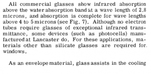
The tube glass is quite thin, and the plate is circa 400-500C for a 6L6 at rated dissipation (there is a nice assessment of this in RCA 1962), so a minor percentage of plate radiation passes directly through the glass (if you look up the transmission characteristic of common glass to wavelength (there is a nice IRCON app note AN109 on this) and do some mental gymnastics for the wavelength emission spectrum of a circa 500C black body. The plate radiation that gets absorbed by the glass then mostly transfers by convection.
You would need to check your FLIR wavelength response, and compare that to the glass characteristic to see how much the FLIR is seeing the glass as opaque.
You would need to check your FLIR wavelength response, and compare that to the glass characteristic to see how much the FLIR is seeing the glass as opaque.
Simple dumm blonde experiment......most literature states that steel will begin to exhibit a red glow somewhere between 400 and 500C, in fact the number 460C is often quoted. So....
Wire up a power supply to a properly connected old tube and crank up the dissipation until the plate begins to glow red.....point the Flir at it and read the number.
I could do the glowing red part easily enough, but I lost my access to a Flir when I left Motorola.
We had a rather nice one with a very expensive lens and mega stable platform for looking at individual transistors on an IC die. It was good for blowing up silicon and other semiconductors on a microscopic scale.......GaN chips will get hot enough to unsolder themselves before they die!
Very interesting regarding the GaN chips- GaN chips are rad hard.
All I know is that the tubes get too hot to touch, but this talk about Stphan-Boltzman and black body radiation made me pull out the college physics and materials science textbooks.
Have to agree with TRobbins regarding convection heating.
All I know is that the tubes get too hot to touch, but this talk about Stphan-Boltzman and black body radiation made me pull out the college physics and materials science textbooks.
Have to agree with TRobbins regarding convection heating.
Is the tube's glass envelope transparent to infrared light, or not?
I'd say not much, since the glass gets pretty @#&^%#$! hot
from the radiation from the plate.
maybe this helps, taken from "RCA 1962 Electron Tube Design"
Attachments
Last edited:
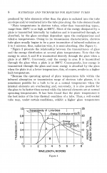
So it seems that much, but not all, of the IR from a hot anode is absorbed by the glass, then some is re-radiated and some is convected. Hence pointing an IR thermometer at a valve will not tell you the anode temperature, and might not tell you the glass temperature accurately either.
There was a thread on here last year about measuring glass temperature. I forget the conclusion, but it was agreed that it was difficult. Glass is not a good black body radiator and its IR properties vary with temperature/wavelength; it is a poor heat conductor so measuring with a thermocouple is not easy either.
There was a thread on here last year about measuring glass temperature. I forget the conclusion, but it was agreed that it was difficult. Glass is not a good black body radiator and its IR properties vary with temperature/wavelength; it is a poor heat conductor so measuring with a thermocouple is not easy either.
Is the tube's glass envelope transparent to infrared light, or not?
I'd say not much, since the glass gets pretty @#&^%#$! hot
from the radiation from the plate.
Very few materials are fully transparent to far infrared. Glass absorbs heavily, all you can measure with a thermal camera or themometer is the temperature of the outside of the glass (and only imperfectly because glass also reflects heat from the surroundings.
The materials that are broadly transparent to far IR heat radiation are the same materials used for thermal camera lenses, basically germanium, silicon, calcium fluoride. zinc selenide, and others.
Some good references:
http://support.fluke.com/ircon-sales/Download/Asset/9260162_ENG_A_W.PDF
1961 RCA, page 261 and nearby.
http://www.lirkorea.com/Landinstruments.net%20Website/infrared/downloads/pdf/temperature_measurement_radiation_thermometers.pdf
I measured the thickness of the glass for a horizontal sweep power tube, and it's circa .027 inch or 0.7mm.
Last edited:
it's very unlikely that this emission would be lambertian, because the emitting surface is very smooth, so the expectation would be to have most radiation coming off at a normal angle to the surface.
This is in fact also discussed in the Application Note mentioned by TRobbins, when they say that the angle under which instrument sees the surface makes a big difference in the reading
Looking at convective transfer data between air and glass it seems that the convection coefficient for "air in the house" is h=10-15 W/m^2K (figures used in architecture to estimate windows heat loss). So the convective heat flow through the envelope should be h*A*\Delta(T). A is ~0.01 so we have one/one and a half watt per 10 deg C difference between envelope and air around it. To move 18W we'd need the envelope at approx 200C (20+180) if it stayed in continuous contact with fresh, room temperature air. If we instead say that the air touching the glass is more like 60C (because it doesn't flow fast enough), the heat exchange rate goes to 14W approx.
Putting the glass radiation and convection transfer mechanisms together we get that glass at 132C radiates away 11.6W and convects away 6.45W. I wonder how one could measure the actual temperature of the glass to verify what's going on here...
On second thought I don't think this idea of using 60C air is sound. I've convinced myself that the whole point of the convection coefficient is to account for air convecting upon contact with the hot surface, and that it's the "room" temperature of the air to use, not the temperature of the air very close to it (which is why I was using 60C). So, putting that back to 20C, we'd get that the envelope of a 6L6 at 113C radiates 9.6W and convects 8.33W, for a total of 17.9W.
The tube glass is quite thin,
0.7-0.8mm according to my caliper, unfortunately the one 6L6 I have at hand that is broken has all the markings rubbed off, and I can't tell what brand it was.
and the plate is circa 400-500C for a 6L6 at rated dissipation (there is a nice assessment of this in RCA 1962),
Well so yes: my spreadsheet says you need 400C of avg temperature to get 31.67W of emission. 430C eyeballing away the "stitching" sides, and only keeping the area of the anode proper. It'd probably be better to reduce it further because the beam forming structure I'll bet creates a substantial shadow on the plate.
(if you look up the transmission characteristic of common glass to wavelength (there is a nice IRCON app note AN109 on this)
Well so. To this: I had posted a like before, from which I thought you could see clearly the absorption wasn't much. However, upon looking for better information I found that Wikipedia says tube envelopes are made of borosilicate glass (see here) because of its low thermal expansion coefficient, which I guess helps keeping the pin sealing tight. Further this Wikipedia page says that common commercial names for this are: Borcam, Borosil, DURAN, Pyrex, Supertek, Suprax, Simax, BSA 60, BSC 51 (by NIPRO), Heatex, Endural, Schott, Refmex, Kimble as well as BK7 and B270.
It also says
Glasses containing 15–25% B2O3, 65–70% SiO2, and smaller amounts of alkalis and Al2O3 as additional components have low softening points and low thermal expansion. Sealability to metals in the expansion range of tungsten and molybdenum and high electrical insulation are their most important features.
This plot from the Crystran manufacturer shows that transmission falls to essentially 0 at about 5um

and do some mental gymnastics for the wavelength emission spectrum of a circa 500C black body. The plate radiation that gets absorbed by the glass then mostly transfers by convection.
So yes, if these plots are more representative of our situation, it seems we'd expect the envelope to be at about 110-120C, for a tube dissipating approx 18W.
You would need to check your FLIR wavelength response, and compare that to the glass characteristic to see how much the FLIR is seeing the glass as opaque.
I got the plot here: I hope to have some time tomorrow to scan it and implement what I think the instrument computes in python, just out of curiosity.
I guess the only thing that remains unexplained is this assertion that all heat is convected away at this point... Even at 170C for the glass you get 30W total dissipation of which 16.65W due to radiation and 13.35W to convection.
Simple dumm blonde experiment......most literature states that steel will begin to exhibit a red glow somewhere between 400 and 500C, in fact the number 460C is often quoted.
I'll look into this when I hook up my python workbook, but my spreadsheet says that a 6L6 anode at 460C (average temp, admittedly) is dissipating 36W, isn't suprising you'd get (mild) replating when you're just 20% above spec? I mean, at 450V this thing is passing 80mA. It's hot, but does it feel hot enough?
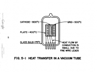
from "Kohl 1960 Materials and Techniques for Electron Tubes"
Attachments
-
 J P Welsh.png39.2 KB · Views: 114
 -
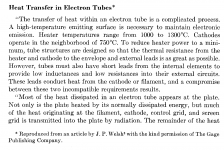 Kohl 1960 Materials and Techniques for Electron Tubes 0.png64.2 KB · Views: 121
 -
 Kohl 1960 Materials and Techniques for Electron Tubes 1.png134.9 KB · Views: 93
 -
 Kohl 1960 Materials and Techniques for Electron Tubes 2.png127.7 KB · Views: 92
 -
 Kohl 1960 Materials and Techniques for Electron Tubes 3.png156.7 KB · Views: 35
So it seems that much, but not all, of the IR from a hot anode is absorbed by the glass, then some is re-radiated and some is convected. Hence pointing an IR thermometer at a valve will not tell you the anode temperature, and might not tell you the glass temperature accurately either.
(PDF) The Potential of Thermophotovoltaic Heat Recovery for the Glass Industry
This paper says (note 14 and 16, page 8) that molten glass is a grey-body radiator of \sigma = 0.9. But the paper below
A Review of Radiant Heat Transfer in Glass | ROBERT GARDON
which I haven't found yet, says in the abstract that heat transfer in transparent glass is complicated by the fact that the "flesh" of the glass participates in the radiant transport. However, I'd suspect that if the absorption at the wavelengths we're looking at is effectively 100% at any thickness of interest, volumetric effects in radiative transport can be ignored, and the material can be thought of as it was opaque, like you would with a piece of obsidian, for example. If that's the case the readout of the glass temperature shouldn't be that far off...
There was a thread on here last year about measuring glass temperature. I forget the conclusion, but it was agreed that it was difficult. Glass is not a good black body radiator and its IR properties vary with temperature/wavelength; it is a poor heat conductor so measuring with a thermocouple is not easy either.
Actually I was thinking about this too. I've seen some 6L6's that has a flattish top instead of a curvy, dome-like one. If the top is flat enoug, maybe using a drop or two of hot glue or wax or oil on the glass and sticking a small thermocouple to it might be a way to get a passable reading.
Of course the top is probably the coldest place of the whole envelope, but still, it might be a start... I wonder what's the melting point of blutack
Jokes aside, anything that will be compliant enough to conform to both the glass and the probe's tip should do if you give it a minute or five to stabilizeWasn't it on Morgan Jones's book to use a piece of single-strand wire to hold a heat probe to the side of a tube? I'll be if it's there for a few minutes the read would be fine.
However I myself got into knots wondering how much of the reading is from radiation and how much if is from conduction...
more to read online:
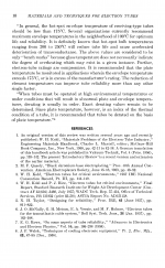
Design manual of natural methods of cooling electronic equipment;
Washington, Dept. of the Navy, Bureau of Ships, 1962
Prepared by James P. Welsh.
vacuum tubes are discussed on pp. 57 ff.
Design manual of natural methods of cooling electronic equipment; ... - Full View | HathiTrust Digital Library | HathiTrust Digital Library
---------------------------------
and also interesting to read online:
Design manual of methods of forced air cooling electronic equipment.
Washington : Dept. of the Navy, Bureau of Ships, 1958.
Cornell Aeronautical Laboratory.
electron tubes on pp. 70 ff.
(the authors mention an "instrumented tube" with a thermocouple welded to the plate)
(not for sale anymore ... ,-)
Design manual of methods of forced air cooling electronic equipment. ... - Full View | HathiTrust Digital Library | HathiTrust Digital Library
Last edited:
- Status
- This old topic is closed. If you want to reopen this topic, contact a moderator using the "Report Post" button.
- Home
- Amplifiers
- Tubes / Valves
- Plate temperature measurement