Working on this Bendix radio and noticed this 6V6 cathode circuit. Is this a form of feedback? Would it be better to directly ground the cathode resistor/capacitor? I had to replace the existing output transformer (not original) with another. I'm sure the specs aren't exactly like the original and the cathode circuit probably won't operate exactly as intended. It does play now and seems okay with the cathode wired this way. I apologize if this has been covered elsewhere.
Attachments
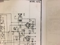
This is cathode feedback. It can work wonders with some OPT's and do nothing with others. I use the same technique on the Tubelab SSE amps with a minor change. Connect the cathode resistor directly to ground, and connect only the negative lead of the coupling cap to the OPT. This keeps the DC out of the transformer and speaker.
You changed out the OPT, so it is possible that the replacement is not phased the same way as the original. If this is the case the feedback could be positive causing loose and flabby bass. You can try swapping the two secondary wires, and choosing the connection that has the lowest volume without changing the volume pot. That will be the negative feedback connection.
You changed out the OPT, so it is possible that the replacement is not phased the same way as the original. If this is the case the feedback could be positive causing loose and flabby bass. You can try swapping the two secondary wires, and choosing the connection that has the lowest volume without changing the volume pot. That will be the negative feedback connection.
Part of the DC bias current will run through the speaker in this design. If you have a known speaker inside an enclosed cabinet, it's properly OK as is. I wouldn't do this if this is used with external speaker terminals, not worth the saving in today's cost of capacitor and resistor.
Part of the DC bias current will run through the speaker in this design..
The DCR of the transformer's secondary is several time lower than the spk DCR, so it is irrelevant.
The DCR of the transformer's secondary is several time lower than the spk DCR, so it is irrelevant.
In this case it probably doesn't matter. The previously mentioned SSE design is a HiFi amp where any speaker could be connected......even a few millivolts of DC will cause noticeable cone movement in a high efficiency speaker like a Lowther, that's why I changed the design early on.
Granted most builders that would use a Lowther, would also use an OPT that didn't need the cathode feedback, but it's better to be safe than .....

I often see this circuit on Philips tube radios. It is mainly a cost reduction measure, I believe. The cathode current is flowing in the output transformer secundary winding with opposite polarity relative to the primary winding anode current. The magnetic fields cancels out and it is possible to use a smaller core; the output transformer on those radios is usually tiny. The output transformer DC resistence is lower than the speaker coil DCR, this way only a small fraction of the DC current is flowing trough the speaker coil.
Audio Research Corp. has used partial cathode coupling in the output stage of their tube amplifiers
since the beginning, and still does. D51D75D75AD76_ManualSchemPL.pdf - Audio Research
since the beginning, and still does. D51D75D75AD76_ManualSchemPL.pdf - Audio Research
pcan,
The current only very partially cancels. Amp x Turns is the operative term. A 5k to 8 Ohm transformer has 25 to 1 turns ratio. Lets say 2500 turn primary, 100 turn secondary
Example, a 6V6 with 29mA plate current, and 3mA screen current, has 32mA cathode current.
2500 turns x 0.029A = 72.5 Amp Turns
100 turns x 0.032A = 3.2 Amp Turns
72.5/3.2 = 22.656 ratio, very close to the 25:1 turns ratio.
The only difference is the additional 3mA screen current that appears in the cathode current, but not in the plate current. 100 x (1/22.656) = 4.4% cancellation of the magnetic fields.
Last edited:
Magnetic field cancellation in an SE OPT isn't the primary reason for doing this. The cathode feedback lowers the dynamic plate resistance of the output tube. In doing so it presents a lower driving impedance to the OPT, such that the low frequency corner will move down slightly for a given primary inductance. It also improves the damping factor of the overall amp.
My testing shows often dramatic improvement when using a small but otherwise decent quality OPT. The Edcor XSE's and Hammond 125 series seem to show a pretty good improvement, while larger OPT's may or may not benefit as much.
Cathode feedback in push pull amps is more of a mixed bag. If the OPT is wound with decent interleaving such that the two primary halves have rather similar and symmetrical coupling characteristics with the 0-4 and 4-16 ohm secondary halves the results can be very good. Trying the same trick with an ultra cheap guitar amp quality OPT (no interleaving at all) will result in an increase in distortion and possible instability at the frequency extremes due to the imbalanced feedback.
My testing shows often dramatic improvement when using a small but otherwise decent quality OPT. The Edcor XSE's and Hammond 125 series seem to show a pretty good improvement, while larger OPT's may or may not benefit as much.
Audio Research Corp. has used partial cathode coupling
Cathode feedback in push pull amps is more of a mixed bag. If the OPT is wound with decent interleaving such that the two primary halves have rather similar and symmetrical coupling characteristics with the 0-4 and 4-16 ohm secondary halves the results can be very good. Trying the same trick with an ultra cheap guitar amp quality OPT (no interleaving at all) will result in an increase in distortion and possible instability at the frequency extremes due to the imbalanced feedback.
When the tube plate pulls the primary toward ground (neg.), the secondary will be moving the cathode positive to produce N Fdbk. So we have electrons going into the neg. phase terminal on the primary, and electrons coming out of the pos. phase terminal on the secondary. Sure looks like the two windings are in phase for current, -increasing- the (DC) magnetic field. A small effect in this case fortunately.
(normal high % primary CFB windings act similarly for the DC, they are just another part of the primary)
I would second Tubelab's mod to keep DC out of the secondary here.
(normal high % primary CFB windings act similarly for the DC, they are just another part of the primary)
I would second Tubelab's mod to keep DC out of the secondary here.
I agree. I've build an amp with 90% primary turns in the anode and 10% in the anode and so the final DC field remains the same. It was as bad (or good) as a 300B SE but much more efficient.. . . Sure looks like the two windings are in phase for current, -increasing- the (DC) magnetic field. A small effect in this case fortunately.
(normal high % primary CFB windings act similarly for the DC, they are just another part of the primary)
. . .

Yves
In this case it probably doesn't matter. The previously mentioned SSE design is a HiFi amp where any speaker could be connected......even a few millivolts of DC will cause noticeable cone movement in a high efficiency speaker like a Lowther, that's why I changed the design early on.
Granted most builders that would use a Lowther, would also use an OPT that didn't need the cathode feedback, but it's better to be safe than .....
One more advantage is, the output is always loaded, so less chances to damage an output transformer clipping the amp with a speaker disconnected.
I often see this circuit on Philips tube radios. It is mainly a cost reduction measure, I believe.
Plilips engineers were most knowledgeable and inventive in that era, and knew well how to use nested feedbacks, unlike others who just copied datasheet examples. It is a sound quality improvement measure, to use a nested feedback loop. Otto Schade from RCA demonstrated advantages of it back in 1938.
However, usage of a speaker output instead of additional feedback loop winding can be a cost reduction measure, indeed.
Yves
That circa 7ma DC running through the loudspeaker won't hurt Yves?
What's the purpose of R5 at the drivers' kathode?
What's the purpose of R5 at the drivers' kathode?
It used to be a global feedback divider resistor?
 and ajusted the cathode current for the screen (45+2)mA
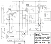
- Status
- This old topic is closed. If you want to reopen this topic, contact a moderator using the "Report Post" button.
- Home
- Amplifiers
- Tubes / Valves
- Cathode Circuit