I built a single ended tube preamp (the circuit is here Sofrito Preamplifier – wauwatosa tube factory). The preamp seems to be working great. By great, I mean that the sound it produces is clean and clear with a bit of :tube:.
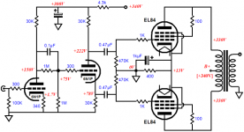
Circuit Schematic:

My build has 2 minor differences:
1. I am using 4.7uF output caps
2. I added a DPDT switch in between the rotary selector switch and volume pot. The inputs ground run to the volume pot and then to the star ground at the output tube (6V6).
However, my amplifier kicked into protection mode the other day about 30 mins into a listening session.
What could cause my amp (Marantz PM8005, input sensitivity is 1.6v 15kohm, running in Power Amp Mode) to go into protection?
Is the addition of my newly built preamp just coincidental? The system was working with out event for ~7 two hour listening sessions. The last session, I got about 30 minutes through a record before the amp went into protection mode.
I removed the DIY preamp from the system, and using the built integrated preamp of the Marantz, and the second half of the record played okay.
What have I tried:
1. I tested the DC voltages from the power supply (after shunt): 330 vDC
Voltage at the 6v6 is 220 v DC as I expect from the load lines in the linked blog post above.
2. While powered on, with no input signal and no output connected, I measured the output RCA ground with multimeter attached to output ground and input ground. DC and AC voltages were 0.
I also measured output RCA ground with meter attached to output ground and chassis earth. This was also 0 (actually, meter read 0.1mV).
When I leave the multimeter attached to output RCA ground and output signal, with no input signal, DC voltages jump all over on my auto ranging MM. Range about is +- 200mV DC
Here is a video of what I am talking about.
YouTube
Other information:
I have a lot of build pics at DIY Stereo Pre-Amplifier Build (Sofrito clone) - Album on Imgur
Here are a couple images so you don't have to scroll through all the build pics:
Power supply section, rectifier tube on top, shunt on bottom

Preamp section:


Thanks for any help, as I am new to the DIY audio space.
I am reluctant to put the unit back into my main system until I think it has been tested a bit more.
PS. Sorry if you saw a similar post on AK, as I asked for help over there too.
Circuit Schematic:
My build has 2 minor differences:
1. I am using 4.7uF output caps
2. I added a DPDT switch in between the rotary selector switch and volume pot. The inputs ground run to the volume pot and then to the star ground at the output tube (6V6).
However, my amplifier kicked into protection mode the other day about 30 mins into a listening session.
What could cause my amp (Marantz PM8005, input sensitivity is 1.6v 15kohm, running in Power Amp Mode) to go into protection?
Is the addition of my newly built preamp just coincidental? The system was working with out event for ~7 two hour listening sessions. The last session, I got about 30 minutes through a record before the amp went into protection mode.
I removed the DIY preamp from the system, and using the built integrated preamp of the Marantz, and the second half of the record played okay.
What have I tried:
1. I tested the DC voltages from the power supply (after shunt): 330 vDC
Voltage at the 6v6 is 220 v DC as I expect from the load lines in the linked blog post above.
2. While powered on, with no input signal and no output connected, I measured the output RCA ground with multimeter attached to output ground and input ground. DC and AC voltages were 0.
I also measured output RCA ground with meter attached to output ground and chassis earth. This was also 0 (actually, meter read 0.1mV).
When I leave the multimeter attached to output RCA ground and output signal, with no input signal, DC voltages jump all over on my auto ranging MM. Range about is +- 200mV DC
Here is a video of what I am talking about.
YouTube
Other information:
I have a lot of build pics at DIY Stereo Pre-Amplifier Build (Sofrito clone) - Album on Imgur
Here are a couple images so you don't have to scroll through all the build pics:
Power supply section, rectifier tube on top, shunt on bottom
Preamp section:
Thanks for any help, as I am new to the DIY audio space.
I am reluctant to put the unit back into my main system until I think it has been tested a bit more.
PS. Sorry if you saw a similar post on AK, as I asked for help over there too.
It would help a great deal if you could mark up the schematic to match what you built. I think I see 2 6V6 and 2 6L6, is that correct? How are the 6V6s triode strapped? No 5U4? SS diodes? Is it dual mono in one chassis or does 1 supply split into 2 regulators at some point? How exactly do the rotary and DP switches wire up?
Could it be mains voltage variation? At first glance it appears that there is a band of frequencies in the subsonic region which will be passed by both the PSU and the line amp output, so any change in mains voltage in this bandwidth will be passed straight through to the power amp input.
Please use a muting circuit with a relay at the output of that preamp to prevent blowing up speakers when the preamp is switched on or off when the power amplifier is still switched on. This counts especially with DC coupled amplifiers but it is simply good practice in any amplifier case. It should release outputs after 30 seconds at power up and it should short the outputs immediately at shutdown. Series resistors 47 Ohm from each of the 1 megaOhm resistors to the relay contacts can make you feel better.
It would also be nice to put simple RC filtering at the inputs to prevent HF/RF straying in. Tube amps are quite robust but solid state amps are a bit more sensitive (in general).
Regarding the issue: could it be that the 6L6 is oscillating?
It would also be nice to put simple RC filtering at the inputs to prevent HF/RF straying in. Tube amps are quite robust but solid state amps are a bit more sensitive (in general).
Regarding the issue: could it be that the 6L6 is oscillating?
Last edited:
It would help a great deal if you could mark up the schematic to match what you built. I think I see 2 6V6 and 2 6L6, is that correct? How are the 6V6s triode strapped? No 5U4? SS diodes? Is it dual mono in one chassis or does 1 supply split into 2 regulators at some point? How exactly do the rotary and DP switches wire up?
There is one power supply that is feeding a stereo pair of 6V6 (as triode). To run the 6V6 as triode, I shorted screen and anode pins (pins 3 and 4). Signal enters the 6V6 on the grid pin (pin 5). B+ (220v DC) is fed onto pins 3/4.
I posted a schematic in the thread to illustrate the wiring of the inputs and switches. Sorry for my rudimentary drawing in advance.
There is one 5U4 rectifier, one 6L6 used as shunt, and 2 6V6 (one for each channel).
BTW, I don't think we ever confirmed how the 6V heaters are referenced to ground. Is there a grounded CT for them or did you make a false CT?
The 6.3v heater and primary have center taps on the transformer. These are grounded in the power supply section at the negative of the first filter cap.
The 5v AC winding from the transformer feeds the 5U4 rectifier heater.
Please use a muting circuit with a relay at the output of that preamp to prevent blowing up speakers when the preamp is switched on or off when the power amplifier is still switched on. This counts especially with DC coupled amplifiers but it is simply good practice in any amplifier case. It should release outputs after 30 seconds at power up and it should short the outputs immediately at shutdown. Series resistors 47 Ohm from each of the 1 megaOhm resistors to the relay contacts can make you feel better.
It would also be nice to put simple RC filtering at the inputs to prevent HF/RF straying in.
These sound like great upgrades to the circuit. I was handling the former by powering up the preamp first and powering down the preamp last.
Do you have any favorite documantation for the above circuit changes. I am new to this, and there is a wealth of information. SOmetimes it is challenging to understand who/what to trust from a google search.
If it helps, the transformer I am using is Hammond Manufacturing 6K7VG
Regarding the issue: could it be that the 6L6 is oscillating?
How can I check that? DC voltage from the 6L6 is steady on my multi-meter (MM).
Would that measure as AC? How would I connect the leads of my MM to measure possible AC at the output of the 6L6?
Was thinking the tubes/valves subforum would give you more exposure.
Is there an easy way to cross post this thread over there, I'd hate to duplicate the thread. Are there any forum precedent for this?
Sorry about posting this link a couple times, but I cannot edit my previous replys


You need to check for ultrasonic oscillation. I had 1 mhz @ 1vac in a mixer I sped up the op amps on, and it sounded okay, but the power amp hated it.
If you don't have a scope, an analog AC voltage multimeter 5000 ohms/volt with 2 vac & 20 vac scales will work. Block the negative probe with .047 600v to prevent the AC scale from reading on DC. If you have output with no sound, very suspicious. You can prove any AC voltage out is ultrasonic by changing the blocking cap from .047 uf to 390 pf. Audio won't pass through 390 pf, but ultrasonic oscillation will.
a 5 v protection diode across the output would prevent huge spikes from destroying your power amp. You also need 33 pf disk caps from center to ring on each input connector to prevent broadcast radio, police/fire/cb band, or cell phone RF from getting into your circuit. You do have a safety grounded metal box don't you? If not, start at the very beginning, a very good place to start. If you have exposed tubes outside the metal case, use ground clip tube sockets and put metal caps over them to prevent RF pickup. Hammond organ did on the H100. Not everybody had a radio transmitter (cell phone) in their pocket in 1930 but many did by 1965. alternately you can put a grounded mesh box over the top to let the hot air out and keep the RF out.
Last edited:
Is there an easy way to cross post this thread over there, I'd hate to duplicate the thread. Are there any forum precedent for this?
No. Keep it here you are getting good responses.
I agree with adding screen stoppers if either of those tubes oscillate you would have problems. It also looked to me like the grid stoppers on the 6V6s might be metal film. I think carbon comp would be a better choice for stoppers.
You need to check for ultrasonic oscillation. I had 1 mhz @ 1vac in a mixer I sped up the op amps on, and it sounded okay, but the power amp hated it.
If you don't have a scope, an analog AC voltage multimeter 5000 ohms/volt with 2 vac & 20 vac scales will work. Block the negative probe with .047 600v to prevent the AC scale from reading on DC. If you have output with no sound, very suspicious. You can prove any AC voltage out is ultrasonic by changing the blocking cap from .047 uf to 390 pf. Audio won't pass through 390 pf, but ultrasonic oscillation will.
a 5 v protection diode across the output would prevent huge spikes from destroying your power amp. You also need 33 pf disk caps from center to ring on each input connector to prevent broadcast radio, police/fire/cb band, or cell phone RF from getting into your circuit. You do have a safety grounded metal box don't you? If not, start at the very beginning, a very good place to start. If you have exposed tubes outside the metal case, use ground clip tube sockets and put metal caps over them to prevent RF pickup. Hammond organ did on the H100. Not everybody had a radio transmitter (cell phone) in their pocket in 1930 but many did by 1965. alternately you can put a grounded mesh box over the top to let the hot air out and keep the RF out.
I just want to make sure I am understanding this correctly. Use an analog volt meter with the listed ranges, Attach the common lead of my multimeter to a .047uF 600v capacitor, which is connected to the ground of the RCA output. Connect the other lead of the multimeter to the output signal part of the RCA. This should read 0 AC volts. If not, there is a problem. Then replace the cap with 390pf and that will only pass the ultrasonic AC.If you don't have a scope, an analog AC voltage multimeter 5000 ohms/volt with 2 vac & 20 vac scales will work. Block the negative probe with .047 600v to prevent the AC scale from reading on DC. If you have output with no sound, very suspicious. You can prove any AC voltage out is ultrasonic by changing the blocking cap from .047 uf to 390 pf. Audio won't pass through 390 pf, but ultrasonic oscillation will.
This test is performed with the preamp powered on with no input signal or output amp connected.
So, just put a diode in line with the output signal for each channel? e.g. output from 6V6 => diode => RCA?a 5 v protection diode across the output would prevent huge spikes from destroying your power amp.
Or are you saying a diode from center to ring on each output connector ?
Great idea! What voltage rating do I need? Probably nothing too large? Is there a favorite you have that doesn't alter sound too much?You also need 33 pf disk caps from center to ring on each input connector to prevent broadcast radio, police/fire/cb band, or cell phone RF from getting into your circuit.
You do have a safety grounded metal box don't you? If not, start at the very beginning, a very good place to start. If you have exposed tubes outside the metal case, use ground clip tube sockets and put metal caps over them to prevent RF pickup. Hammond organ did on the H100. Not everybody had a radio transmitter (cell phone) in their pocket in 1930 but many did by 1965. alternately you can put a grounded mesh box over the top to let the hot air out and keep the RF out.
I have a safety grounded top plate, with exposed tubes. The transformer has grounded covers and an additional transformer cover is attached to the top plate. All internal signal wires are shielded cable. The sides of the chassis are wood. The bottom is acrylic.
Sorry for all the extra questions. I do realize this is a lot, so thank you in advance.
No. Keep it here you are getting good responses.
I agree with adding screen stoppers if either of those tubes oscillate you would have problems. It also looked to me like the grid stoppers on the 6V6s might be metal film. I think carbon comp would be a better choice for stoppers.
Thanks for the heads up on the grid stoppers. I am not sure where to add a screen stopper on a 6V6 in triode. Is it just another high value resistor? Where would I wire it?
So, my grid stopper is wired between grid and input signal and is 300 ohm. Does adding another 100 ohm resistor between grid and screen cause me to change the grid stopper value? How does one choose a value for the screen stopper resistance? Is 1/4 watt resistor okay? Or higher?
I think the confusion came from my use of the term "screen grid" . what we usually call the grid is more properly called the control grid. There are three grids is a pentode the control grid (aka grid), the screen grid (aka screen), and the suppressor grid (aka suppressor).
Thanks for this clarification, it is helpful. I am putting together a replacement parts list now. Really wish I had a local store to stop at, as I end up paying shipping so many times...such is life. Eventually, I will end up with a bunch of extra parts bin.
Now I have to dig into some reading to figure out what @indianajo meant about a 5v protection diode and what type of 33pf caps to use on the inputs?
Now I have to dig into some reading to figure out what @indianajo meant about a 5v protection diode and what type of 33pf caps to use on the inputs?
Last edited:
Here is a bidirection TVS diode that starts clamping at 6.4 v https://www.newark.com/multicomp/1-5ke7-5ca/tvs-diode-132a-11-3v-bi-directional/dp/91R0686
It's $.55 there is a 5 v one but it is $3.55 Tubes could produce 250 v bangs if something came loose & reconnected. 33 pf input RF filter caps can be 50 v rated or higher. The ceramic disks I'm using were in a Radio Shack grab bag from the 70's still have a few dozen. Cheap X7R are suitable for this use. Reputable ceramic disk vendors are Vishay, Aerovox, Kemet.
The AC meter oscillation test can be done both with a signal and with the input shorted. Music will show up as .1 to 2 vac through a .047 uf filter cap. I find rock music useful for tracing signals through faulty circuits, you can see the beats of volume in the pointer of the meter. Oscillation will show up as a steady voltage through the 390 pf cap, which won't pass any music 20-20000 hz. Found some bad solder joints by chasing music through an amp with the simpson 266xlpm VOM on 2 vac (in the front part) or 20 vac (in the back part).
If you're not getting RF oscillation or interference, don't worry about covering with metal. I get an AM radio station, also a CB radio that drives by emitting dogs barking "dixie" on my amps without a faraday (grounded metal) cage. Took a 68 pf across the input to get rid of the AM radio station. Sports talk radio, how vile!

- Home
- Amplifiers
- Tubes / Valves
- DIY Tube Preamp causing Power Amp Protect Mode