Does anyone know if Relays introduce noise into the Power Supply if they are used to switch the Power on/off and the HT on/off (stand-by function)?
My plan is to replace the two 240V toggle switches in the common design to use 240V and 300VDC Relays instead, switched from a240V rotary 3P3T switch. The switch would be Off in p1, Stand-By in p2 and On in p3.
This is for a stereo integrated amp that I am building from scratch using ECC83's and EL34's.
Roger and out
First : do not switch the B+. There is no need and it can make more damage to the tubes then you like.Does anyone know if Relays introduce noise into the Power Supply if they are used to switch the Power on/off and the HT on/off (stand-by function)?
My plan is to replace the two 240V toggle switches in the common design to use 240V and 300VDC Relays instead, switched from a240V rotary 3P3T switch. The switch would be Off in p1, Stand-By in p2 and On in p3.
This is for a stereo integrated amp that I am building from scratch using ECC83's and EL34's.
Roger and out
Second i would recommend SSR ( solid state relay ) for the task, they make and break at zero crossings, thus no pops or bangs.
Se the wikipedia intro :
Solid-state relay - Wikipedia
then search your favorite vendor for samples.
I switch B+ and power the relay from the bias supply. If it fails, the output tubes are disconnected from B+. I put the relay on the DC B+ line (under 400V) and use one of these.
Waterproof Car Relay DC 12V 40A 4Pin Automotive Fuse Relay Normally Open Relayvb | eBay
Waterproof Car Relay DC 12V 40A 4Pin Automotive Fuse Relay Normally Open Relayvb | eBay
An introduction to SSR :
https://www.electronics-tutorials.ws/power/solid-state-relay.html
And some devises for sale :
https://www.electronics-tutorials.ws/power/solid-state-relay.html
The really nice thing is that those relays may be controlled by logic circuits, such as a microprocessor or even simpler a 9V battery (that would last forever)
A simple switch closure will connect the battery to the device, turing on. When turned on a voltage, basically anything, will "hold" the relay on, another switch that shorts the SSR control will turn off. The end effect is that two cheap switched will turn on and off a device using no mains voltage at the switches and doing this job silent and without disturbances.
https://www.electronics-tutorials.ws/power/solid-state-relay.html
And some devises for sale :
https://www.electronics-tutorials.ws/power/solid-state-relay.html
The really nice thing is that those relays may be controlled by logic circuits, such as a microprocessor or even simpler a 9V battery (that would last forever)
A simple switch closure will connect the battery to the device, turing on. When turned on a voltage, basically anything, will "hold" the relay on, another switch that shorts the SSR control will turn off. The end effect is that two cheap switched will turn on and off a device using no mains voltage at the switches and doing this job silent and without disturbances.
Turning power OFF always makes "noise". Relay same a s a switch. (Non-issue for turn-ON because tubes don't work right away.)
AC coil relay will throw hum around the chassis.
The only switch I would use on B+ is the Carling vacuum-cleaner switch which has served well on a million Fenders. Relays to switch 400V into a capacitor are rare and never rated for such work. If I "HAD" to relay a B+, I would start with the relay for a whole-house air-conditioner. It may stand the strain; if it fails every year they are readily available at competitive prices (<$20).
Bridge the B+ (HT) relay contacts with a capacitor and resistor in series.
This will do two important things:-
a) Considerably ease the turn-off stress on the contacts. Instead of the HT load current causing the relay contacts arcing over, it's shunted into the capacitor until it charges to the B+ voltage.
b) stops the generation of turn-off transients which get into other places and cause the noise.
Size the capacitor to substantially charge in about 6-7 millisec. The resistor protects the relay contacts from overcurrent surge when they close. A resistance of the same order as would draw the load current from B+ will be about right. Use a resistor of 1 Watt rating or higher - not to handle the dissipation, which can be regarded as negligible, but to withstand the voltage.
Make sure the relay contacts are rated to switch significantly more than the B+ voltage or it won't last long. Any HT filter electrolytics should be before the relay contacts to protect them from the charge-up surge. Or, if you have a vacuum tube rectifier, you can get away with a filter cap after the relay contacts.
A better solution is to have separate transformers for B+ and heaters. Then you can standby switch the AC input to the B+ transformer, which doesn't stress the contacts and a cheap relay can be used with great reliability.
Last edited:
Most relays and switches are not rated for high voltage DC - its hard to break a DC arc if enough power is available to sustain it. Typically the current limiting of a vacuum tube circuit as load prevents the arc growing too big. For a high power vacuum amp I'd be very cautious about switching anywhere other than the AC supply.
As a datapoint a 1200V 0.5A supply of mine (basically big transformer / bridge rectifier / series stacked electrolytics) can hold an arc upto about 2cm in diameter. You'd need a Frankenstein-style knife blade switch to handle that!
As a datapoint a 1200V 0.5A supply of mine (basically big transformer / bridge rectifier / series stacked electrolytics) can hold an arc upto about 2cm in diameter. You'd need a Frankenstein-style knife blade switch to handle that!
First : do not switch the B+. There is no need and it can make more damage to the tubes then you like.
Second i would recommend SSR ( solid state relay ) for the task, they make and break at zero crossings, thus no pops or bangs.
Se the wikipedia intro :
Solid-state relay - Wikipedia
then search your favorite vendor for samples.
Be careful of the spec sheet. Not all SSRs switch at zero cross. The ones that do will specify such. The ones that don't may say nothing.
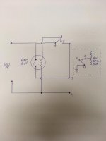
Attached a drawing of the delay arrangement i use for direct heated triodes.
one amperite time delay tube, one relay: https://no.mouser.com/datasheet/2/307/my_ds_e_7_3_csm59-940997.pdf
one amperite time delay tube, one relay: https://no.mouser.com/datasheet/2/307/my_ds_e_7_3_csm59-940997.pdf
Attachments
Using a 240V switch to power a 240V relay to power the amp seems peculiar unless the amp takes so much power than such an arrangement is necessary. For an EL34 amp it is not necessary and simply adds cost, complication and unreliability. There is no need for a stand-by switch; it may do little harm if you get it right, but it won't do any good. For over 70 years ordinary domestic amps have used a simple mains switch, because that is all that is needed.
Using a 240V switch to power a 240V relay to power the amp seems peculiar unless the amp takes so much power than such an arrangement is necessary. For an EL34 amp it is not necessary and simply adds cost, complication and unreliability. There is no need for a stand-by switch; it may do little harm if you get it right, but it won't do any good. For over 70 years ordinary domestic amps have used a simple mains switch, because that is all that is needed.
20 years production of tube-based TV sets with silicon diode voltage doubler power supplies too. No tube rectifier warn-up lag in those to avoid stressing the other tubes warming up.
BUT:-
1. Delaying HT switch-on does give a small tube lifetime advantage - a somewhat larger advantage in larger more expensive power tubes - that's why Tektronix for example had a thermal relay (Amperite) to delay HT switch-on in their more expensive CRO's.
2. In stage band applications, musicians like to have a "standby" feature - where the heaters are kept warmed up and ready, but there's no HT and a completely silent amp until it's that musician's turn to play.
Last edited:
Relays to switch 400V into a capacitor are rare and never rated for such work. If I "HAD" to relay a B+, I would start with the relay for a whole-house air-conditioner. It may stand the strain; if it fails every year they are readily available at competitive prices (<$20).
I use a 12V relay for automotive duty. I also switch B+ after the capacitors, not before to avoid the current spike on connection. It'll switch 320V easily, and since the contacts are 40A rated, they last for years. Never had one fail yet.
Thank you all for your contributions to this "crazy" idea I had, they were all good but different.
The history of this is that a Guitar Amp would have typically have had a Power Switch, that powers the transformer with 120 or 240V, and a Stand-By Switch in the HT with 350VDC (forgive me, I generalise!). My thought was why not do the same with a stereo HiFi Amp? However, the Amp I am building today is designed to have a Rotary Power Switch so I thought "why not combine the two switches in on and that would force me to start the Amp in Stand-By.
I know there are opposing camps on whether a Stand-By switch is good or bad so I expected some people to say "don't do that" and others to either offer creative suggestions or tell me why HiFi Amps should not have a Stand-By.
I have tried to summarise the suggestions:
1. Use a much bigger relay like one used in home appliances. (I like the Frankenstein chopper switch idea... it's awake!).
2. Use a solid-state relay and/or a DC coil as "AC coil relay will throw hum around the chassis" (that answers the question about noise).
3. Use a relay to short a dropping resistor to apply full negative bias to reduce or cut off the current through the EL34s . (That is creative, I like it!).
4. If you are going to use a relay then "Bridge the B+ (HT) relay contacts with a capacitor and resistor in series".
My conclusion so far is that this was an interesting thought exercise but maybe HiFi Amps do not have Stand-By switches due to the cost of producing the necessary hardware... or do you know another reason?
Applying power to the heaters without current flow (no B+) will lead to cathode poisoning. I used to wire a B+ switch so the amp was ready to go when I needed it, but the tube life suffered. New KT88s that were low on emission within a month. YMMV, but unless you have EHT B+ (600+ volts) I wouldn't bother. The only exception being when there is a bias supply that could fail, then I use that to enable B+ so if the bias fails, the tubes don't red plate.
Using a 240V switch to power a 240V relay to power the amp seems peculiar....
My understanding was that he proposes a rotary switch to sequence the start-up. Off, Heat, HV.
Since high-current rotary switches are a hidden corner of the world (motor controls, not electronics), he's using common rotary switch for the logic sequence and relays for the power.
"Changeover" switches:
Changeover Switch 4 Position Rotary Selector Cam 8 Terminals Latching Ith 20A 714998077820 | eBay
Rotary Changeover Switch 440V 20A 1-0-2 3 Position Three Phase Panel Tool US | eBay
Mounting Rotary Select Cam Changeover Switch AC 660V 20A 16 terminal 5-Position 711811395376 | eBay
These rarely explain the switching, and many are center-off which is not what the application wants.
An old alternative (Dynaco had it on the BIG tube amp) is a relay with a time delay. This needs no user training. It won't stall at hot cathode and dead HV, kodabmx's objection. Time-delay relays are now hard to get.
Of course there are situations where you leave the heaters hot (or half-hot) with dead B+: instant-on TV the notorious example.
Last edited:
Applying power to the heaters without current flow (no B+) will lead to cathode poisoning.
Only if the tubes are already faulty from poor manufacture or overstress in use.
If there is a slow leak between a pin and the glass (happens due to poor factory technique, or over temperature in use due exceeding ratings or poor ventilation), there is a very slow build-up of oxygen from the atmosphere inside the tube. The gettering absorbs this, but its ability to do that depends on being hot enough for a large enough fraction of time.
Oxygen is nasty to cathodes.
In small signal tubes, you may have heater power 6.3V x 0.3A = 1.9 W, anode dissipation = (say) 150 V x 0.5 mA = 0.075 W. So it makes no discernable difference whether you have HT on or not.
In a KT88, heater power is 11.3 W and anode & screen dissipation is 50 W. So a KT88's gettering works a heck of a lot better when HT is on, providing heat for the gettering.
There is another problem discovered in wartime computers, where a tube in a flip-flop might stay cut-off for hours or days at a time. It was found in the 1930's that adding certain elements to the cathode nickel increases emission. But if the tube was drawing no HT current, it caused a semi-insulating layer to build up between the nickel and the oxide. The tube actually retained full emission, but with a resistance now in the cathode, it lost gm.
Once this was discovered, tube manufacturers went back to pure nickel. You are unlikely to encounter this problem now. Or did you buy Chinese tubes??
This reminds me of an old dodge to revive battery tubes like 1T4, 1R5, etc. By necessity, these drew so little current, dissipating only about 0.08 W, the gettering in service was just about useless. You could sometimes revive a weak one by cooking it in an oven at 200 C for an hour.
Last edited:
It won't stall at hot cathode and dead HV, kodabmx's objection. Time-delay relays are now hard to get.
Of course there are situations where you leave the heaters hot (or half-hot) with dead B+: instant-on TV the notorious example.
I use these for time delay: DC 12V Relay Module Adjustable Delay Time Switch 0-10 Second Bo NE555 W3W6 P8J2 | eBay
Yes, I had an RCA TV with Instant on. Original tubes worked for 40 years. Not perfectly, there was a VLin issue which I referred to as "The lake at the bottom of the screen". Especially noticeable on a low line voltage.
Last edited:
Only if the tubes are already faulty from poor manufacture or overstress in use.
If there is a slow leak between a pin and the glass (happens due to poor factory technique, or over temperature in use due exceeding ratings or poor ventilation), there is a very slow build-up of oxygen from the atmosphere inside the tube. The gettering absorbs this, but its ability to do that depends on being hot enough for a large enough fraction of time.
Oxygen is nasty to cathodes.
In small signal tubes, you may have heater power 6.3V x 0.3A = 1.9 W, anode dissipation = (say) 150 V x 0.5 mA = 0.075 W. So it makes no discernable difference whether you have HT on or not.
In a KT88, heater power is 11.3 W and anode & screen dissipation is 50 W. So a KT88's gettering works a heck of a lot better when HT is on, providing heat for the gettering.
There is another problem discovered in wartime computers, where a tube in a flip-flop might stay cut-off for hours or days at a time. It was found in the 1930's that adding certain elements to the cathode nickel increases emission. But if the tube was drawing no HT current, it caused a semi-insulating layer to build up between the nickel and the oxide. The tube actually retained full emission, but with a resistance now in the cathode, it lost gm.
Once this was discovered, tube manufacturers went back to pure nickel. You are unlikely to encounter this problem now. Or did you buy Chinese tubes??
This reminds me of an old dodge to revive battery tubes like 1T4, 1R5, etc. By necessity, these drew so little current, dissipating only about 0.08 W, the gettering in service was just about useless. You could sometimes revive a weak one by cooking it in an oven at 200 C for an hour.
In my case it was half heat (AC heater string running through a diode) and Chinese KT88... After this, I got rid of the B+ delay (and the Chinese power tubes) after reading information that cathode stripping only happens at transmitting tube voltages... Never seen a domestic radio or amplifier with a B+ delay except as I said when the C- supply is a separate SMPS. Obviously having an amp come up to operating voltage without bias is a BAD idea, but the 12V that runs the SMPS can run a relay, too. And for the record, I switch B+ after the caps but before the OPTs.
This is all anecdotal, I find now that "audio" tubes are marde when compared to an amp running trioded Soviet sweep tubes...
You could also revive a tube with interface resistance by applying double the heater voltage. Not good for it, but it was already phucked, right? They actually had something like this for worn out CRTs... It went between the tube and the socket to boost heater voltage.
Last edited:
- Status
- This old topic is closed. If you want to reopen this topic, contact a moderator using the "Report Post" button.
- Home
- Amplifiers
- Tubes / Valves
- Using Relays to switch Power and HT (stand-by)