I am getting conflicting advises regarding B+
From the WoS site
"If the voltage is not between 75 and 85 volts resistor R12 will need to be changed.
Use a lower resistance if the voltage is too low, use a higher resistance if the voltage
is too high."
From @Goatguy
"B+ of 104 volts unloaded, and 94 volts loaded does not sound out-of-spec."
if I do adjust the R12 to get between 75 nd 85v, from the 20ohm resistor, what would be an ideal resistance to use?
Because of the common power supply for filament and B+ the values for R12 and R15 can be SLIGHTLY co-dependant. More important than the B+ voltage is making sure the filament voltage doesn't go too high. Personally I wouldn't let it drift above about 24.5 volts. B+ can go a bit higher than recommended and you shouldn't have any grief.
Once you are happy with the filament and B+ (only measured with the tubes in, tubes out measurements don't mean much) measure the voltages across R2 and R11 as detailed on pages 12 & 13 in the WOS link below.
Be aware that the Aikido circuit can be somewhat sensitive to tubes that have mismatched triodes. As well, because the input and output tubes are direct coupled (no capacitor) one tube can sort of "pull" the other around.
Steve
https://wallofsound.ca/wp-content/u...ges-Part-4-chassis-assy-trans-wiring-test.pdf
Hi All,
I'm in the middle of building the Aikido 12VAC preamp. In the build manual, it is suggested that R13 be calculated based on the following formula:
R13=R10 X ((33-2)/(33+2)) .
That results in a value of 300X(31/35) = 265 Ohms. But the recommended value of R13 is 88.7K ! But I see pics of several builds[pics] with R13 of 88.7K ohms and R10 of 300 ohms. Can anybody please confirm?
OOPS, Sorry guys.
Some of the confusion is down to me and some to the relabelling of board components between revisions of the board. The initial release of the board DID NOT have the two Zener diodes. On this board the filament dropping resistor is labelled R11 and the B+ dropping resistor is R12. The board drawing on the Glass-Ware site is of the earlier version of the board.
The newer version WITH the Zener diodes labels the filament dropping resistor as R15. This relabeling avoids confusion with two other resistors in the amplifying section of the board labelled R11. The pictures on the WOS site are the later version of the board WITH Zener diodes.
The schematic, page 6, in my first version of the 12Vac has three R10s. The one in the "middle" that connects to ground should be R16, which is 100K ohms. R13 which connects to C1 and R10 (2x) and R16 should be 88.7K The middle resistor labeling has, I think, been corrected in later versions of the manual and definitely on the board.
I'm assuming you are building the 6DJ8 version and NOT the 12AU7 version of this amp. The 12AU7 version will have many different Component values compared to the 6DJ8 version.
I hope I haven't made this as clear as mud. If you follow all four parts (and the multiple attachments with each part) on the WOS site your should finished board should be correct and the amp work properly.
If the B+ runs a bit high don't worry. The circuit runs the tubes quite conservatively so even a bit more B+ won't put the tubes anywhere near their dissipation limits. Watch the filament voltage though. Running this too high will shorten tube life!
Cheers, Steve
I built a 6GM8 version of the Aikido on the original board that was sold. It worked the first time off the bench and has been running ever since. It's probably been over 10 years at this point. This one uses a 24vdc open frame linear regulated power supply that supplies both B+ and heater voltage. 24/4 = 6vdc, a little low but still works just fine. The only mod I've done over the years is to put in a remote selector/volume control. It doesn't actually change anything in the underlying circuit.
The biggest problem is that the price of 6GM8 tubes has gone through the roof. I bought my original quad for $4 apiece, and these were Amperex Bugle Boys. I bought another quad as backup soon after and all of these are still the ones I use. Some day I'll need to buy new again.
In a similar fashion, I've been using Sovtek 6B4G in my amp and after a few early failures I've had the same quad for a very long time now. But just today I got an email from TubeDepot and they have a black Friday sale on these so maybe it is time to buy a backup quad.
Last edited:
The schematic, page 6, in my first version of the 12Vac has three R10s. The one in the "middle" that connects to ground should be R16, which is 100K ohms. R13 which connects to C1 and R10 (2x) and R16 should be 88.7K The middle resistor labeling has, I think, been corrected in later versions of the manual and definitely on the board.
I'm assuming you are building the 6DJ8 version and NOT the 12AU7 version of this amp. The 12AU7 version will have many different Component values compared to the 6DJ8 version.
...
heers, Steve
Yep, 6DJ8 version. And thanks Steve for clearing the confusion. I guessed it would be R16 in the formula as it was the only 100K resistor
") . But the build guide emphasised on the formula for R13 calculation, hence wanted to be sure.
. But the build guide emphasised on the formula for R13 calculation, hence wanted to be sure. PS: among the resistors supplied in the kit, only 88.7K seems to be of 1/4 watt rating. Will it be able to withstand the current or should i replace it with 1/2 watt one? Or bit of variation is fine as i see a 84k Dale resistor there in the pack meant for R13.
PPS: is it possible to post the soft copy of the latest version of manual here?
Last edited:
1/4 watt is fine for R13 (the 88.7K). There is very little current flowing through this resistor and it is all AC, essentially the noise (AC) riding on the DC from the power supply. Likely in the range of a few millivolts.
Sorry, can't post the manual, it is copyright material.
Cheers, Steve
Sorry, can't post the manual, it is copyright material.
Cheers, Steve
zcastre, was it the Aikido LV you built?
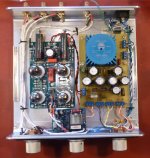
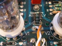
I had a LV board and did a little creative hacking to boost the B+ to about 48 volts. I copied the power supply part of the 12Vac on a separate proto board. See pic. Using a 9 volt trannie lowered the B+ but still gave me a bit more than 24 volts for the filaments. The normal power in on the board got the B+ but the filament supply was connected to the board between V1 and V2. See pic. I also installed the zener mod here too. I had to cut a few board traces to separate the filament from the B+. Each triode of a 6GM8 will handle 30 volts so two "stacked" in an Aikido will handle 60 volts. With 48 volts R2 & 4 were set to 220 ohms, R8 & R11 180 ohms.
I also put in a remote volume kit, a cheapo found on eBay.
It sounds decent but doesn't quite have the drive and pace of a 6DJ8 version of the 12Vac.
If you need 6GM8s PM me. We might be able to do a deal.
Cheers, Steve
Attachments
1/4 watt is fine for R13 (the 88.7K). There is very little current flowing through this resistor and it is all AC, essentially the noise (AC) riding on the DC from the power supply. Likely in the range of a few millivolts.
Sorry, can't post the manual, it is copyright material.
Cheers, Steve
Thanks again Steve!
R15 [20ohms, 3W] on my build is getting really hot on powering up and i can smell it's burning. I turned it off within a minute or so - didn't get a chance to test voltages.
I've used all recommended values of resistors from build guide. What would be the next step? I checked all the polarities - everything looks fine

I've used all recommended values of resistors from build guide. What would be the next step? I checked all the polarities - everything looks fine
Last edited:
Can you see anything burnt/blackened? Sometimes power resistors might just smell hot when they are working correctly.
Depending on your line voltage and the transformer used the voltage applied to the power supply might be too high.
Try about a 100 ohm resistor for R15. It might be an iterative process to get the right resistor.
A 3 watt rated resistor for R15 seems a bit too low. My build had two 51 ohm, 3 watt resistors in parallel, together dissipating a maximum of 6 watts (3 each) and they both got pretty warm.
It looks like your plan is to have the tubes on the top side of the board and all of the rest of the components on the bottom. You might want to put R15 on the top, spaced say 2mm above the board for better cooling.
Good luck, Steve
Thanks Steve for your responses!
Yep, I saw R15 smoking and turning black.
Input voltage as measured is around 12.4Vac - I use a servo stabilizer.
For R15: I started with 24 ohms resistor rated at 5W, even that started smoking. Later changed it to much stout looking 35 ohms resistor. Even that smoked.
Later, based on qguy2000's posts : changed the R12 from 1K ohms to 2K ohms - this time around R15 didn't smoke - but eventually it started glowing Red.
All these checks are being made without inserting tubes : don't want to destroy them. Hope I'm doing it correct?
I do not have 100 ohms resistors of higher wattage rating with me - will try again with those resistors later.
Yep, I changed the position to top for both R12 and R15.
Including the resistor values used in the build - just to be sure. If I'm not wrong qguy2000 has made use of different resistor values.
R1,5,6,7 : 1M
R2,4 :180
R3,9,10 : 300
R8,11 : 100
R13 : 88.7K
R16 : 100K
R12: tested with 1K and 2K
R15: 20 3W, 24 5W and 35 [not sure of the watts - this is the guy flowing red in the below pic]

Can you see anything burnt/blackened? Sometimes power resistors might just smell hot when they are working correctly.
Yep, I saw R15 smoking and turning black.
Depending on your line voltage and the transformer used the voltage applied to the power supply might be too high.
Input voltage as measured is around 12.4Vac - I use a servo stabilizer.
Try about a 100 ohm resistor for R15. It might be an iterative process to get the right resistor.
A 3 watt rated resistor for R15 seems a bit too low. My build had two 51 ohm, 3 watt resistors in parallel, together dissipating a maximum of 6 watts (3 each) and they both got pretty warm.
For R15: I started with 24 ohms resistor rated at 5W, even that started smoking. Later changed it to much stout looking 35 ohms resistor. Even that smoked.
Later, based on qguy2000's posts : changed the R12 from 1K ohms to 2K ohms - this time around R15 didn't smoke - but eventually it started glowing Red.
All these checks are being made without inserting tubes : don't want to destroy them. Hope I'm doing it correct?
I do not have 100 ohms resistors of higher wattage rating with me - will try again with those resistors later.
It looks like your plan is to have the tubes on the top side of the board and all of the rest of the components on the bottom. You might want to put R15 on the top, spaced say 2mm above the board for better cooling.
Good luck, Steve
Yep, I changed the position to top for both R12 and R15.
Including the resistor values used in the build - just to be sure. If I'm not wrong qguy2000 has made use of different resistor values.
R1,5,6,7 : 1M
R2,4 :180
R3,9,10 : 300
R8,11 : 100
R13 : 88.7K
R16 : 100K
R12: tested with 1K and 2K
R15: 20 3W, 24 5W and 35 [not sure of the watts - this is the guy flowing red in the below pic]
Last edited:
Wow
That resistor glows! Does it do that when the tubes are installed too?
Disconnect one end one of the zeners and remove C10. On C10 put a little heat on one lead then pull it out a mm or so. Do the same with the other lead. Go back and forth applying heat alternately to each one until the cap comes free.
Apply AC to the board and if R15 still glows there is short circuit somewhere in the filament circuit.
What's a servo stabilizer? Just pain old AC from a toroid trannie or wall wart should be fine.
Steve
That resistor glows! Does it do that when the tubes are installed too?
Hi Steve,
R15 glows with the tube installed too - though takes bit of time. Strangely, tubes didn't glow at all. On my first power up with the stock resistor values of R15 [20ohms] and R12 [1K] tubes were glowing faintly.
I also measured the DC Voltage across R15, it was around 30+ volts.
After removing tubes, Output caps and disconnecting only one end of the Z1 Zener, R15 didn't get hot. Rather measured DC Voltage across R15 was negligible. Planning to go back to 1K ohms for R12 and current value of R15 [30 ohms] along with the tubes and check. Will do this tomorrow. This time around will measure Voltages even if resistor glows red.Disconnect one end one of the zeners and remove C10. On C10 put a little heat on one lead then pull it out a mm or so. Do the same with the other lead. Go back and forth applying heat alternately to each one until the cap comes free.
Apply AC to the board and if R15 still glows there is short circuit somewhere in the filament circuit.
Any other ideas for trouble shooting! Else, will hold off on experimenting until I get my hands on 100 ohms 6+Watts resistors for R15.
Yep, using a R Core trannie for 12 VAC. Mentioned about Servo stabilizer as I use it to set the correct Primary voltage for tranny.What's a servo stabilizer? Just pain old AC from a toroid trannie or wall wart should be fine.
Steve
Last edited:
Maybe just remove R12 and leave it out until you get the filaments sorted out.
Were the tube in with the latest measured voltage across R15? If not it isn't surprising, no filament current draw = no voltage drop across R15.
Maybe you have a bad C10 cap and/or a bad Zener. Leave them out/disconnected for now. Use the 100 ohm resistor for R15 to start. Install the tubes and see what happens.
Can you vary the voltage to the input of the transformer? If you can start low and ramp up the voltage gradually.
Check you circuit board for any solder bridges across places where they're not meant to be.
Once everything is working you might want to solder as many parts as possible on both sides of the board. I like to as it is more mechanically and electrically secure.
Steve
Maybe just remove R12 and leave it out until you get the filaments sorted out.
Were the tube in with the latest measured voltage across R15? If not it isn't surprising, no filament current draw = no voltage drop across R15.
Maybe you have a bad C10 cap and/or a bad Zener. Leave them out/disconnected for now. Use the 100 ohm resistor for R15 to start. Install the tubes and see what happens.
Can you vary the voltage to the input of the transformer? If you can start low and ramp up the voltage gradually.
Check you circuit board for any solder bridges across places where they're not meant to be.
Once everything is working you might want to solder as many parts as possible on both sides of the board. I like to as it is more mechanically and electrically secure.
Steve
Hi Steve,
I changed the R12 back to 1k and disconnected zener and output caps.
Retained the 25 ohms resistor as i still couldn't get the 100 ohms one.
I measured the villages: B+ voltage was around 85 volts. And every other voltage was same as per the pdf manual! And the R15 didn't glow or smoke even after 5+mins (voltage across R15 was around 12+ volts).
On connecting the zener back , tubes didn't even glow and the R15 was getting hot again( R15 voltage was now 30+volts) . What do you suggest? Should i get a replacement zener or can i leave it out altogether?
PS: thanks for diagnosing the zener issue!
Last edited:
Leave the Zeners out if you wish. The first version of the 12Vac didn't have them. What filament voltage do you get with the 25 ohm res? Monitor the filament voltage from first switch on to make sure it doesn't get too high before the tubes warm up. If it doesn't forget about the zeners.
If you are concerned about high filament voltage during startup a 3 pole, 3 position switch will help control that. Let me know and I'll share the circuit if you wish.
S.
If you are concerned about high filament voltage during startup a 3 pole, 3 position switch will help control that. Let me know and I'll share the circuit if you wish.
S.
Hi Steve, i disconnected the zener and measured the voltages again:Leave the Zeners out if you wish. The first version of the 12Vac didn't have them. What filament voltage do you get with the 25 ohm res? Monitor the filament voltage from first switch on to make sure it doesn't get too high before the tubes warm up. If it doesn't forget about the zeners.
If you are concerned about high filament voltage during startup a 3 pole, 3 position switch will help control that. Let me know and I'll share the circuit if you wish.
S.
Filament voltage : I'm getting 23 volts ( across z1 and z2). It rises slowly to around 23 volts and stays there after power up.
B+ voltage is 84.5 volts
Between jumper and R2 voltage 0.86 (close to V4 tube) and R2 voltage of 0.75 volts on the other side
R11 voltage is 0.48 volts (same on both sides)
Except for R2 voltage near V4 (range specified in pdf is 0.6 to 0.8) , everything else is within the range!
I checked the output voltage for AC with shorted inputs. It almost didn't register any reading.
Now I'm yet to solder the output caps.. waiting for voltages to drain out..
Last edited:
- Status
- This old topic is closed. If you want to reopen this topic, contact a moderator using the "Report Post" button.
- Home
- Amplifiers
- Tubes / Valves
- Glass-ware Aikido 12vac build