Yes. One thing often lost in these discussions is that the main goals of designing a power supply, like at the top of the list are:
• № 1 - quiet, ripple-free DC output
• № 2 - stiff variable-load regulation
• № 3 - reasonable line-variation independence
• № 4 - piped in A/C noise suppression
• № 5 - very high reliability
• № 6 - inexpensive implementation
• № 7 - possible slow-turn-on HV ramp
Thing is … there is “another way”, that is equally inexpensive, yet optimizes all 7 criteria. Requires some sand … but so silicon rectifiers be!
Using symbol S as 'series regulator', the optimum topology is basically:C₁LC₂SC₃
Just saying,
GoatGuy ✓
Your seven points are good, except for the last one. A slow turn-on ramp is good because it prevents thumps in your speakers. But a CRC with modern large electrolytics gives you that.
But you went horribly wrong on reliability. Since you can get silicon diodes with ratings that considerably exceed circuit voltage, mean current, and peak current, cheaply, the reliability of silicon rectifiers is impeccable. I fixed vast numbers of tube TV sets in my earlier days, and NONE of them had crook rectifier diodes. Same with tube stereo amps. Lab test gear. Silicon diode reliability and robustness is excellent.
But tube rectifiers - rectification is very hard on oxide cathodes. Tube manufacturers did the best they could, but tube rectifiers have always been the weak point in tube equipment, reliability-wise. That's why American manufacturers dropped them as soon as low cost silicon diodes became available, but tubes in signal stages stayed in volume production for another 20 years. Military equipment used selenium rectifiers, which were costly in high reliability forms, far from perfect, but a lot better than tubes. Germany, which was not s cost conscious and knew early on how to make good selenium rectifiers, used them instead of tube rectifiers from the 1930's onwards.
MOSFET's in this application reliable - you have to be joking.
To get reliability, follow these well established principles:-
1. Use as few parts as possible. Use large values rather than lots of parts.
2. Don't use a tube rectifier
3. Over design it. If (say) you need 600V PIV diodes, use 1000 V diodes. If you need ripple less than (say) 100 mV, design for 25 mV. That allows for some electrolytic deterioration over the equipment lifetime.
4. Put the electrolytics where they will stay cool. (eg away from tube rectifiers). Choose the right spot on the chassis, use above chassis can types, put the choke between the caps and power dissipating devices, etc. On, if you are using one or more chokes, consider block oiled paper capacitors instead of electrolytics, which are just about indestructible.
5. Don't use any MOSFETs (or bipolar silicon for that matter)
Back in the tube era, apart from the later years, manufacturers of high reliability professional equipment used oil filled caps and avoided electros. But modern electros are better, especially in large microfarad sizes.
A single CLC filter can always be designed to meet the same half-way reasonable ripple spec as a CLCLC AND be a lot more reliable, and also have a slower turn-on. But it will do that by using larger size parts, and may be more expensive.
Last edited:
If you for example, or anyone else for that matter, wish to implement your power supply using hand-made selenium rectification stacks in conjunction with hydrogen-mercury vapor rectification, by all means. Go for it.
GoatGuy ✓
Those on this forum who obtain and use mercury vapour rectifiers worry me. Mercury is VERY nasty stuff.
Sooner or later a tube is going to be accidentally broken, and folk made ill by the mercury.
Those who leave their tubes on full display are really taking a risk. There is little real danger from some visiting little kid breaking a signal tube, even with HT on, and even with power tubes, he's likely to only get a severe shock. But with mercury vapour tubes he's going to end up in hospital, or perhaps dead. Shock risk (AC in the tube) and poisoning.
Mercury vapour rectifiers were never intended for home equipment. They are dangerous, and put out ultraviolet light too.
The transient voltage at the beginning also depends on the DCR of the secondary ... the DCR of the primary also is a factor...
True and true; also in "this" section many folks use vacuum rectifiers with large internal resistance.
My kneejerk thought was that large R in the first choke would have a disproportionate effect on output voltage, but that was wrong. There's no peak surge. There is simple Idc*R loss, but any decent choke has low loss this way.
Those on this forum who obtain and use mercury vapour rectifiers worry me. Mercury is VERY nasty stuff. Sooner or later a tube is going to be accidentally broken, and folk made ill by the mercury. Mercury vapour rectifiers were never intended for home equipment. They are dangerous, and put out ultraviolet light too.
Did I need to put up the [sarc]…[/sarc] tag? Sorry!
Anyway, regarding the prior-to-that post, I'll offer to simply disagree gracefully.
I have designed both bipolar and MOSFET (and IGBJT) low-to-medium power 24-to–576 volt quadrature (4 phase) and 3 phase motor controllers using these venerable pieces of silicon, and I can say this from experience: the voltages, current spikes, flyback EMF, and rectification snubbering required for real-world motor controllers to survive years of service without a hiccup, is perhaps 2 orders of magnitude more demanding than series-regulation of a HV power supply for a sweet little (or giant!) audiophile grade DIY amplifier.
The single biggest problem (naïve) designers run into is actually exactly what you cite in your advice section. UNDER-spec'ing the MOSFETs and BJTs that do the heavy lifting. Or underestimating the temperature of the undercarriage of the amplifier, and not providing a way for the regulators to slough off the heat-of-regulation. Those are the killers. And parts that are too sketchy to begin with for the service they're to provide.
Again… peace, Keit.
Diff'rent strokes, diff'rent folks.
GoatGuy ✓
The loss through resistance in the circuit when using cap input filters is (I squared) x R. The impulse is short for cap input filters (as PRR reminded me earlier). Lots of DCR equals lots of energy loss for a short time period.
But (I) squared reminds me of Physics, and impulse momentum, which in some cases is 1/2 x M x (V Squared).
A car traveling 5 MPH runs into a brick wall. The same kind of car traveling 10 MPH runs into a brick wall. The force is 4 times that of the 5 MPH car.
Things squared, can become a factor to calculate.
The choke input filter has a much smoother current (as PRR reminded us).
The lowest switching noise diode for use with tube amplifiers has been measured and documented = TV damper diode (Matt Kamna), they may be wrong but it worked for me; stupendously well.
Hey 6A3, if its okay to PM: I like what you write and have some ideas with which you may be able to assist with.
Please send me a PM.
Best wishes to all,
HK
Hey 6A3, if its okay to PM: I like what you write and have some ideas with which you may be able to assist with.
Please send me a PM.
Best wishes to all,
HK
Last edited:
Patrick Turner did a very informative webpage about chokes and tube psu....powertranschokes
The loss through resistance into cap-input filters is I²R. The impulse is shorter for cap input filters the larger the cap value. Lots of DCR equals lots of energy loss (GoatGuy: in the transformer secondary and somewhat, the primary) for a short time period.
But I² reminds me of Physics, and impulse momentum, which in some cases is ½ x M x (V Squared). GoatGuy: um … ½mv² is kinetic energy…
A car traveling 5 m/s runs into a brick wall. The same car traveling 10 m/s runs into a brick wall. The energy is 4 times that of the 5 m/s car. GoatGuy: The momentum is only 2× though. EK = ½mv², but u (momentum) = mv;
Things squared, can become a factor to calculate.
The choke input filter has a much smoother current (as PRR reminded us).
I've inserted corrections and comments in the quote.
The basic 'problem' needing address is that while P = I²R (power in a resistance), mean power is E = P(t) = I(t)²R. One has to “integrate” I(t)² to get a sense of E (energy), and E/Δt for the average power over the interval.
The larger the capacitor being charged, the smaller the charging time and ultimately, the higher the current flow.
So… we're saying the same thing, sort-of, but from more precise angles. I'm not sure the car-brick-wall analogy is all that helpful.
Just saying,
GoatGuy ✓
Patrick Turner did a very informative webpage about chokes and tube psu....powertranschokes
He sure did. I've been reading this all afternoon, after you posted it. Fabulous work, actually.
Over the last few weeks, being a kind of goat that likes reinventing wheels, I have been quite fruitlessly trying to model choke-input circuit dynamics, using 10 µs simulation clock, and all the usual primary values.
I can report with almost giddy glee, that as of this afternoon, after throwing out in disgust my code now, 4 times … and having to build it up from scratch every time … that my values for VRMS ripple correspond exactly to the values posted by Patrick Turner in his monograph. I cannot express how happy that makes me … because “the code” doesn't have any cheats in it.
We just came back from the grocery market, and I have a pair of delightfully marbled Wagu steaks which is my reward/treat … for me an the Wife. She's had to glower at me repeatedly over the last 2 weeks as my yet-another-iteration of the code … failed … and failed… and so forth.
Yay!
GoatGuy ✓
Tuned Choke in PS
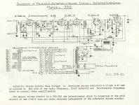
The choke tuned by a paralleled cap was used quite often in radios in the 30's & 40's. At that time electrolytics were costly, by comparison chokes were cheap. The LC combination of the L & Paralleled C were set to the 2nd harmonic of the power frequency. But above that frequency the filter is not as effective as without the paralleled cap. In the example the choke is the field coil for the loudspeaker, the cap is C18.
A possible exception is where a shunt capacitor is used across the choke in a phase cancellation scheme - this can give very low ripple with small components. This technique is rarely used.
The choke tuned by a paralleled cap was used quite often in radios in the 30's & 40's. At that time electrolytics were costly, by comparison chokes were cheap. The LC combination of the L & Paralleled C were set to the 2nd harmonic of the power frequency. But above that frequency the filter is not as effective as without the paralleled cap.
In the example the choke is the field coil for the loudspeaker, the cap is C18.Attachments
> above that frequency the filter is not as effective as without the paralleled cap. In the example the choke is the field coil for the loudspeaker, the cap is C18.
An interesting plan.
As you say, the "choke" is also the field coil. Variation of coil voltage will modulate the force on the voice coil causing 120Hz+ intermodulation. While the 120Hz may be tolerable, the harmonics of it may give very queer effects on music even speech. The cap could be intended to cut those harmonics.
Maybe the field coil works somewhere way up into saturation or something. What seems wacky to me is the lack of a power supply cap (to ground) at the output transformer primary. ???
This old stuff actually worked, but it's hard to tell from here how well.
All good fortune,
Chris
This old stuff actually worked, but it's hard to tell from here how well.
All good fortune,
Chris
> above that frequency the filter is not as effective as without the paralleled cap. In the example the choke is the field coil for the loudspeaker, the cap is C18.
An interesting plan.
As you say, the "choke" is also the field coil. Variation of coil voltage will modulate the force on the voice coil causing 120Hz+ intermodulation. While the 120Hz may be tolerable, the harmonics of it may give very queer effects on music even speech. The cap could be intended to cut those harmonics.
Using the speaker field as the power supply choke was the normal approach before decent alnico speaker magnets became available post World War 2. Even in high quality equipment. I have restored a number of radiograms and radios of best quality of the time of manufacture, and there's not a trace of audible hum, nor of any hum modulation.
Permanent magnet speakers were only used back then for portable radios and for professional speakers where the speaker was remote or sold separately from the amplifier.
These pre-war speakers worked well as a choke because the magnetic circuit design meant a high level of leakage inductance. At the same time they worked well as speakers without audible hum modulation because the pole pieces surrounding the voice coil acted as massive shorted turns. Also, the pole pieces only were operated in saturation. Thus, in the voice coil and voice coil airgap, the DC component from part of the field coil flux passed, but the AC component for practical purposes was suppressed. The AC component of the flux, and the remainder of the DC component bypassed the pole pieces and voice coil.
Don't worry - those pre-war speaker engineers knew what they were doing.
C18 is given as 0.07 uF. That is too low to suppress hum effectively by resonating with the speaker field coil. Probably they built a prototype, and without an electro bypassing the HT end of the output transformer, the only return path for signal is through the 600 ohm resistor R16 to the main HT line electro. That should work ok as 600 ohms is a lot less than the transformer primary impedance, probably 5000 ohm or more. But perhaps the prototype had some funny secondary effect or instability at HF, and somebody discovered that C18 cured it, a lot cheaper than another electro.
That "Majestic" circuit is far from typical of the day. It has AGC, an RF stage, and a separate triode oscillator, and is not an autodyne like most radios and radio grams were before the pentagrid age. It has push-pull detection, which gave an improvement in sound quality with the low IF frequency (175 kHz versus 455 kHz used later) used with early superhets. It thus has pretentions of significantly better than typical quality. The weak point is the single (not push pull) directly heated output pentode. There will be a degree of hum modulation there, though it would be extremely low unless the tube is reaching the end of its life. There also no negative feedback, post war this was considered essential with pentode output (but not with beam tetrodes, which are more linear).
Chris - yes, the soft iron was worked into saturation, which reduces the variation of flux.
Keit - Thank you too much for your typing. Yes the old guys knew much more than we do today.
The lack of 2nd cap IS quite odd, to the point I wonder if it is a typo. The 310 is very similar but has 8uFd at the 2nd node.
Keit - Thank you too much for your typing. Yes the old guys knew much more than we do today.
The lack of 2nd cap IS quite odd, to the point I wonder if it is a typo. The 310 is very similar but has 8uFd at the 2nd node.
Attachments
The lack of 2nd cap IS quite odd, to the point I wonder if it is a typo. The 310 is very similar but has 8uFd at the 2nd node.
Given the presence of the 600 ohm resistor, you are quite likely right. There is another possibility - I have no idea whether it would apply to the Majestic.
One of the smaller manufacturers here in Australia was bit dodgy. They employed a competent engineer who would come up with a good circuit, using a goodly amount of ripple suppression and HT decoupling, grid stopping resistors, etc in accordance with good practice. But the technical cretin owner also employed an old technician whose job it was to look for cost savings. This chap would, without bothering much amount understanding the consequences, remove parts one by one and listen to see if there was any difference. If he removed a cathode bypass he could plainly hear the marked loss in gain, but if he took out a HT bypass, the effect might be nil or very subtle. So the sets were sold with parts not installed. Half the service jobs on these sets was putting the missing bypasses and grid stoppers back in. A change of tube and away they would go, oscillating or motorboating.
Another possibility is that the 600 ohm resistor was added later after prototype testing.
Last edited:
One thing that made the radio work well with a (low) 175kHz IF, was the fact that there were 2 RF tuned circuits plus 1 oscillator tuned circuit (3 gang capacitor).
The 2 tuned circuits was good enough to get rid of the undesired image conversion (called image rejection). The added RF amp gave good sensitivity, while the oscillator/mixer single triode had enough signal to make the mixer output strong for the IF stages.
But Radios with 455kHz IF often used just 1 RF tuned circuit, and 1 oscillator tuned circuit, and the oscillator and mixer was one pentode (or even 6 or 7 element tube). That used a cheaper 2 gang capacitor. And there was no RF amplifier.
I believe some later designs that used the speaker field coil as the B+ filter choke, also employed a Hum-Bucking coil, to get rid of the residual hum.
Car radios on the other hand, often used an RF stage. And the tuning was often done by using multiple (3) slug tuning, thereby eliminating the 3 gang capacitor.
And there was no hum from power mains, but you did get hum when you passed near or underneath high tension power lines.
Last edited:
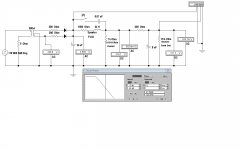
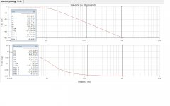
1935 Receiver Power Supply Performance Simulation
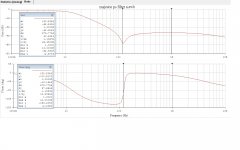
A simulation of the 30s receiver's PS shews how effective the resonated choke can be at the rectified frequency. And how the filter is less effective above. In the simulation the key 'Z' switches the resonating cap in or out of the cct.
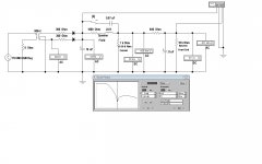
The receiver is a Majestic, one of the Rogers Radio versions. At that time most of Southern Ontario (Toronto) was on a 25 Hz power system, while the rest of the country was on 60 Hz. So Rogers had to built two versions. Thus, two values of are C18 shewn. The sim is for the 60 Hz version. We got on 60 Hz around 1949, no more flickering lights.
There are resisters in both the primary & secondary of the PT to reflect reality. Should be some resistors in series with the electrolytics as well, next time. The speaker field coil at 1.5K is typical. The output tube plate is not as critical so is less filtered. And the speaker would not likely reproduce much 120 Hz.
Attenuation of the rectified frequency is best at the resonance point. But above that flattens out. Winding capacity of the choke would limit the effectiveness at higher frequencies of both circuits.
A simulation of the 30s receiver's PS shews how effective the resonated choke can be at the rectified frequency. And how the filter is less effective above. In the simulation the key 'Z' switches the resonating cap in or out of the cct.
The receiver is a Majestic, one of the Rogers Radio versions. At that time most of Southern Ontario (Toronto) was on a 25 Hz power system, while the rest of the country was on 60 Hz. So Rogers had to built two versions. Thus, two values of are C18 shewn. The sim is for the 60 Hz version. We got on 60 Hz around 1949, no more flickering lights.
There are resisters in both the primary & secondary of the PT to reflect reality. Should be some resistors in series with the electrolytics as well, next time. The speaker field coil at 1.5K is typical. The output tube plate is not as critical so is less filtered. And the speaker would not likely reproduce much 120 Hz.
Attenuation of the rectified frequency is best at the resonance point. But above that flattens out. Winding capacity of the choke would limit the effectiveness at higher frequencies of both circuits.
Attachments
Last edited:
I believe some later designs that used the speaker field coil as the B+ filter choke, also employed a Hum-Bucking coil, to get rid of the residual hum.
Car radios on the other hand, often used an RF stage. And the tuning was often done by using multiple (3) slug tuning, thereby eliminating the 3 gang capacitor. And there was no hum from power mains, but you did get hum when you passed near or underneath high tension power lines.
Hum Bucking OPTs were also often used on the small AC/DC radios. During my Internship at U of T Physics I was on the poor side of the tracks, but in one of the surplus stores I found the incomplete chassis of a radio that would fit my 1953 Ford. It had the permeabilty RF front end complete. I managed to cobble together the rest of the pieces & had music in my car. The IF was 465 KHz. It had a vibrator operated PS, the vibrator ran at 115 Hz.
HV power lines created interference most often in wet weather.
Eventually I built an SW all-band convertor in a separate aluminum box. In those daze that was fairly common. So the whole setup was double conversion.
Attachments
- Status
- This old topic is closed. If you want to reopen this topic, contact a moderator using the "Report Post" button.
- Home
- Amplifiers
- Tubes / Valves
- DCR requirments for Chokes