Designing a tube amplifier would be good to start with the published tube data.
At the page 2 of the attached data you can find the conditions of PP amplifier at AB1 with fixed bias.
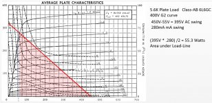
According to the tube manufacturer, 55 W out require 450 V plate voltage and 5k6 as load impedance.
Here is a just a quick and dirty number crunch to show the GE data is valid...however I do not agree with the curve fitting... This assumes a higher idle voltage...
Attachments
Based on your measured DC voltages during operation...My calculations show roughly 50W with that plate load and tubes...
If you were to have the 8 Ohm load on the 4 Ohm tap, then would explain everything ....
Damn, I was so excited about this post but everything appeared OK when I checked. After driving the primary with a sine wave, I measured the voltage at each tap and there it got progressively smaller from 16 to 4 ohms, which is what we would expect.
I did however find that the secondary common connection was a bit weak so I touched that up and found I could get an extra 2W or so, but that's it.
Grid leak resistors on the OP stage, seem a bit high too, not checked the datasheet for 6L6GC in fixed bias but would suspect it to be lower than 220k. Try 47k - 100k and try reducing G2 R's to 100r also.
This is just tweaking though, measure the OP of each stage at full whack to make sure your getting enough IP to g1 - g1 of the 6L6's in open loop.
Those are the typical grid leak values used for guitar. My concern with lowering them is the extra load on the PI from the master volume, which then could run out of juice.
I am suspicious of the PI in that it appears to distort first, but I have seen it overdrive 6L6s cleanly so I'm unsure.
I'll check again as you describe!
I would try the 4R and the 16R output taps on 8R load just in case the turns ratio is not optimal.
I tried this whilst measuring the voltage on the dummy load and the voltage decreases at both 4 and 16, so it's looking like 8 is optimal. I was hoping to find otherwise tho, lol.
Your Pi/driver can't push current into 6L6 grids hence you can't go in AB2 and, with indicated voltages you are limited to less than 30W. Your amp is perfectly functional.
The simplest way to reach 50W could be to replace the 6L6s for EL34s, readjust the bias and tie the 8 ohm load to the 16 ohm terminal.
Will run if the power supply can supply twice the actual intensity.
Yves
The simplest way to reach 50W could be to replace the 6L6s for EL34s, readjust the bias and tie the 8 ohm load to the 16 ohm terminal.
Will run if the power supply can supply twice the actual intensity.
Yves
Your measuring equipment needs to be verified...
Are you scoping the output signal at the load ???Make sure it is at the hairy edge of symmetrical clipping ??
I think they are fine. The scope and the meter agree with each other, for instance, when the meter reads 10V, the scope will show +/-14V, which would be the peak value of 10V RMS.
I do scope the load, yes, and if I'm interpreting "hairy edge" correctly, it does appear that clipping happens symmetrically. The top of the waveform distorts slightly before the bottom.
Your Pi/driver can't push current into 6L6 grids hence you can't go in AB2 and, with indicated voltages you are limited to less than 30W. Your amp is perfectly functional.
The simplest way to reach 50W could be to replace the 6L6s for EL34s, readjust the bias and tie the 8 ohm load to the 16 ohm terminal.
Will run if the power supply can supply twice the actual intensity.
Thank you, Yves! Could you help me understand how you arrived at this conclusion? I believe you are right, but I'd like to learn how to be able to calculate/determine that!
Could you help me understand how you arrived at this conclusion? I believe you are right, but I'd like to learn how to be able to calculate/determine that!
Cerrem's load line in post 18 for actual measured voltages at full power looked OK to me, so I too would be interested in why only 30W would be expected.
Designing a tube amplifier would be good to start with the published tube data.
At the page 2 of the attached data you can find the conditions of PP amplifier at AB1 with fixed bias.
According to the tube manufacturer, 55 W out require 450 V plate voltage and 5k6 as load impedance.
One thing confuses me about that datasheet. On page 2 under Push-Pull Class AB1...two valves, the power out under the 3800 ohm P-P impedance and the 6600 Ohm P-P columns look like they are swapped.
One thing confuses me about that datasheet. On page 2 under Push-Pull Class AB1...two valves, the power out under the 3800 ohm P-P impedance and the 6600 Ohm P-P columns look like they are swapped.
Has to be given everything else is equal aside from plate current.
But looking at those datasheet numbers, it still makes no sense that 30W is the max I can get from this circuit. If we look at the plate and screen voltages, mine at are at 430V Va and 420V Vs, which are far closer to the 55W example than the (likely) real 26.5W, which is basically what I'm getting. Plus my OT has a lower impedance. Something has to be wrong here.
When calculating plate loads and power output....You need to take into account the voltage you will have when the amp is at full power.... Do not use quiescent idle voltages for these calculations....
You can play with multiple combinations of plate loads and voltages and get similar output powers...However, you will have all different results with respect to the total harmonic distortion results...
As for why your power level looks to low, I suspect your signal is clipping in a preceding stage...
...page 2 under Push-Pull Class AB1...two valves, the power out under the 3800 ohm P-P impedance and the 6600 Ohm P-P columns look like they are swapped.
Correct as printed. With just 270V on G2, in AB1, the 6L6 can't pull 360V into the low 3,800r load. Contrast with the AB2 listings. By taking grid 1 high (pulling grid current, it *can* pull a 3,800r load.
These ratings come from the older 6L6 sheets. AB2 was still a valid option (driver transformers were commonplace). There was not a large selection of load ratios. "3800 Ohms" appears to have been a standard way to get 38 Watts out of a 1608 transmitter triode, so I suppose a Standard Part. 6L6 in AB2 will do a little more power, at lower B+, and less grid drive. It is a "boast", but the context has gone out of fashion.
I am suspicious of the PI in that it appears to distort first, but I have seen it overdrive 6L6s cleanly so I'm unsure.
Pull the output tubes and scope the grid pins at the sockets to verify that your driver can put a bit more undistorted drive into the grids than they will need.
I have run a Tubelab universal PP driving 6P3S-3 (6L6oid) tubes with UL taps at 400V B+ and a 5K opt and gotten 40W out in AB2 at 8%thd. I only got 20W before I hit grid current.
I have managed to squeeze over 110 watts out of a pair of old 6L6GA's in AB2 into 3300 ohms before a tube arc spoiled the fun. Those boards have a mosfet buffer between the PI and the output tubes so that the grids can be driven positive. The 6L6 types respond well to AB2 and can put out plenty of power.
When calculating plate loads and power output....You need to take into account the voltage you will have when the amp is at full power.... Do not use quiescent idle voltages for these calculations....
You can play with multiple combinations of plate loads and voltages and get similar output powers...However, you will have all different results with respect to the total harmonic distortion results...
As for why your power level looks to low, I suspect your signal is clipping in a preceding stage...
I see. I suspect the PI, but I do think I see it overdrive the 6L6 grid with a clean signal when I scope there. The top of the waveform gets flat fast, right around the same amplitude as the bias voltage. It's not a smooth transition to clipping, the edges are sharp, which I assume is evidence the PI can't drive the 6L6 grid positive?
What are the specific output transformers used in this amp?
Ratings, brand, etc.
It's a Classictone 40-18001. 4.2k primary with 16, 8, 4 ohm taps. 50-60W.
No driver can push the grid vary far positive through a cap. That's why the Tubelab board uses a mosfet for driving the grid directly.
It is not clear whether your driver circuit can swing enough drive voltage WITHOUT any 6L6 grid to drive, that's why I asked. The drive gets clipped with the tube in place. Does it still get clipped in the same place without the output tube? If so, you need to fix that before worrying about the output stage.
Your terminology and schematic looks like that this may be for a guitar amp application? If that's the case you don't want to hit the 6L6's hard enough to keep it in the serious positive grid zone because long term overdrive (crank it to 11, connect up a pedal board full of overdrive boxes, and beat on it for an hour or so) can fry a grid.
Pull the output tubes and scope the grid pins at the sockets to verify that your driver can put a bit more undistorted drive into the grids than they will need.
Ok, I'll run this test today.
I have managed to squeeze over 110 watts out of a pair of old 6L6GA's in AB2 into 3300 ohms before a tube arc spoiled the fun. Those boards have a mosfet buffer between the PI and the output tubes so that the grids can be driven positive. The 6L6 types respond well to AB2 and can put out plenty of power.
That's insane! What happened when the tube arc'd? I'm imagining fire and brimstone, lol.
- Status
- This old topic is closed. If you want to reopen this topic, contact a moderator using the "Report Post" button.
- Home
- Amplifiers
- Tubes / Valves
- Can't get full power