You can share a single divider chain to bias both MOSFET gates.
The reason for two, is that i dont want to use matched tubes.
Drive the input stage constant current source from 0V, not 250V, then the resistors can run far cooler...
This one is just embarrassing, thank you for pointing it out
")
You lack a discharge cap on the input capacitor, so it will hold voltage when unplugging a source. Suggest move the 1M to the input jack, replace the 1M with 47k standard input load resistor. This will reduce noise when the input is unplugged.
So you would not have a resistor from grid to gnd? or would you have a 47k at the jack, and something else at the grid?
With 400pf of gate source cap the mosfet will just couple the output of the first stage straight to the grid of the output at HF. You will find the mosfet is making no difference. You could use an emitter follower. You only need a few volts on the collector as the grid only needs to go just above 0v. This would reduce power dissipation the the semiconductor. Maybe 100k on the anodes is too high. Try simulation at 10KHz sinewave.
It wont see 400pF, since it is a source follower, so the gate-source capacitance is bootstrapped. so it is mainly the gate-drain capacitance that is left.
I do however have some problems in my current simulation.. So.. I return to answer and post the current schematic, when it is solved
Ok, so everything is working again
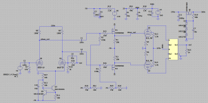
I have attached an updated schematic the main differences are:
I have one big question at the moment (or a few...). Is a dominant pole necessary, if I have some compensation in the feedback network?
Also, were would it make most sense to make frequency compensation?
I can put a capacitor between the outputs on the ltp. or capacitors from the same points, but connected to ground. And of cause, do as I already do.
Are there other places I can compensate?
And thank you all again, the help is greatly appreciated!
I have attached an updated schematic the main differences are:
- More control over screen voltage and added screen resistors
- Lower drain voltage on source followers
I have one big question at the moment (or a few...). Is a dominant pole necessary, if I have some compensation in the feedback network?
Also, were would it make most sense to make frequency compensation?
I can put a capacitor between the outputs on the ltp. or capacitors from the same points, but connected to ground. And of cause, do as I already do.
Are there other places I can compensate?
And thank you all again, the help is greatly appreciated!
Attachments
Don't do that, trust me on this. You might be able to get away with PP pentodes without any NFB if you're using something like the 6V6 or a TV HD type like the 6BQ6. Without gNFB, the 6L6-oids will sound really bad, as this type likes to make higher order harmonics. Even though the STC Report has THD= 1.8%, that's a bit misleading. That's what I measured, however, the residual after nulling out the fundamental looked like a near perfect sawtooth at three times the frequency -- lots of H5 and higher. That leads to a sonic effect as annoying as fingernails on a blackboard. With the 6BQ6, that residual looked like a slightly distorted sinewave: mostly H3 with a trace of H5. Even though the amplitude was higher (THD= 3.0%) the sound was mainly overly "aggressive", but not nasty. Add just enough gNFB to take the "edge" off.
The 6L6-oids need the assistance of NFB in order to sound their best.
This is really interesting I would never have seen this comming... I kinda have to try for my self. Not that I dont believe you, but it would make a good exercise.
I really have to remember that different tubes are so incredibly different... Compared to transistors were I can make an ok amp with almost any power transistors in the output. I dont know if this is true.... but right know it feels true, tubes are confusing
Last edited:
250V for MOSFETs is too high, you will fry control grids on transients, you need to limit their current on peaks. .....
Ohh this is a really good point, thank you! points like this is exactly why I made this thread.
I would still make provision for g1 resistor for the 807 on your pcb....even if you use a small value or link initially. I would also consider a 22 ohm fusable resistor for the plate. After all if the valve shorts then at least you save your output transformer.
See also the use of MOSFETS on Voltage Followers
Good luck. Interested to here how it sounds.
See also the use of MOSFETS on Voltage Followers
Good luck. Interested to here how it sounds.
I plan to have the 807's off the PCB, so I will put the G1 resistor on the socket. Even though i dont really know how important distance is, with tubes. But when i do switching circuits with mosfets, it is really important.
The actual mosfet I am going to use has zeners integrated, so it should be safe.
And about the 22ohms, wouldn't a fuse on B+ give me the same security?
And thank you, I have all the parts, the pcb is underway, and the top plate design is almost finished. So it is moving forward
The actual mosfet I am going to use has zeners integrated, so it should be safe.
And about the 22ohms, wouldn't a fuse on B+ give me the same security?
And thank you, I have all the parts, the pcb is underway, and the top plate design is almost finished. So it is moving forward
Wherever you decide to create a dominant pole, do not do the following:
An increase of resistance of R15 and R16.
The characteristic of the MOSFETs is that as the Gate voltage swings, the capacitance of the gate changes.
I doubt you want a 'Swinging Frequency' Dominant pole.
I remember a few solid state amplifiers that used complimentary MOSFET totem pole source follower outputs.
Each of those amplifiers used a swamping capacitor(s) from the MOSFET gates to ground. That caused the driver to have a heavier load,
but that load did not change appreciably with the changing gate voltage (and consequential changing gate capacitance).
Last edited:
I have one big question at the moment (or a few...). Is a dominant pole necessary, if I have some compensation in the feedback network?
Also, were would it make most sense to make frequency compensation?
I can put a capacitor between the outputs on the ltp. or capacitors from the same points, but connected to ground. And of cause, do as I already do.
Are there other places I can compensate?
The Eico ST-70 transformers are excellent; you'll have a fine amplifier. You've chosen a difficult course, with pentode (high gain, high output impedance) outputs, but an excellent topography. Pentodes are like snub-nose revolvers, an expert's weapon, hard to use well but great if used right.
If I could suggest a location for the dominant pole rolloff it would be in parallel with anode-to-grid feedback at both output valves, what folks here are calling "Schade" feedback. Signal from the MOSFET's sources would be "built out" with appropriate series resistors.
I recommend this for two reasons: 1) lowering the source impedance to the output transformer helps to minimize its footprint.
And, even more important for beginning homebrewers, 2) it puts the feedback where it's needed and not in a long, tricky loop all over Creation (and around the output transformer, as depicted and too often used, without any Zobels or other considerations).
Your proposed schematic almost uniquely encourages doing this right, and with its inherent differential input is quite remarkable.
All good fortune,
Chris
Yes you may well need a dominant pole to bring the loop gain down to say 6dB before the poles of the transformer kick in.
I would aim for say 17dB of NFB. To do this you will need a simulation model of the transformer. You will need primary inductance, primary resistance, secondary resistance, mutual coupling and primary capacitance. The last two are almost impossible to measure. I did this by taking the real transformer onto a dummy load with source resistance the same as 2*plate. Sweeping it with a sig gen and measuring the primary and secondary voltages and phase with a scope. I then did the same thing in simulation and adjusted Cp and M do that I got a good match up to 500KHz.
Roughly the first zero R26/C9 should cancel the first pole of the transformer (50-70KHz usually). The dominate zero should be say 3x lower than this say 12-15KHz. You can break the FB path in the simulator and get a bode plot.
Hope this helps.
Last edited:
I really have to remember that different tubes are so incredibly different... Compared to transistors were I can make an ok amp with almost any power transistors in the output. I dont know if this is true.... but right know it feels true, tubes are confusing
That's the difference between high gain devices like transistors and low gain devices. Even in a low gain topology, the behaviour of a transistor circuit is largely independent of the active device (BJTs mainly). Unless you need some special characteristic, like an unusually low noise figure, it doesn't matter much what type of transistor you use so long as it can process the highest frequencies of interest. I've done lots of projects with those packets of "transistors anonymous" Rat Shack used to sell.
With tubes, it's different since these are low gain devices, and circuit performance is a good deal more dependent on the characteristics. That's why "tube rolling", especially where NFB isn't being included, can get you a different sound.
You can try and listen with the gNFB disconnected. It won't stay that way for very long.
OK you may need to drop the values of C1 and C2. At the LF end if the pole of the transformer is similar to that of C1/R3 you will get poor phase margin here (motor boating). You should arrange C1/R3 to be the dominate pole. It also helps in preventing the transformer becoming saturated if there is a big LF signal. Maybe C1=C2=10 or 22nF
Last edited:
- Status
- This old topic is closed. If you want to reopen this topic, contact a moderator using the "Report Post" button.
- Home
- Amplifiers
- Tubes / Valves
- Sanity check on 807 pp amp, before pcb design