Well, I certainly would think some level of measurement and engineering care would at least point you in the right direction, to ensure quality sound. And I would like to believe what makes sense in the experience of measuring something and engineering it has a positive correlation to the psycho-acoustic experience of listening.
In other words, as a hobby it becomes fun when these two mesh and you made it so. Including the timeless benefit of having it for, say, the rest of your life. Confident in the certainty that everything's pretty much just right. If something new and radical is happening and its for real, you can certainly try it out. You have your reference.
I swapped out my 4" Fostex I've been listening to for the 8" KEF Concentrics for a bit and when I put these Fostex back (in a new cabinet no less) I felt that I had missed them. In my heart. So, I'm talking about two electro-mechanical devices here; related to, well, levels of pleasure. The Fostex are just such a pleasure to listen to - I cant even listen to the KEFs anymore. Psychology connected to sound quality. Sound quality connected to some understanding, engineering and successful measurements. Or in my case - sheer luck. Thinking about it, perhaps not so easy to measure, but I bet you could measure it.
Seems also relevant at cathode bypass duty.... I once observed a phenomenon when a push-pull amplifier powered from electrolytic capacitors produced intermods on top frequencies similar to balanced SSB modulator. They were pretty small, but still audible, as a smeared stereo soundstage of cymbals, triangles, etc. Shunting 2x470 uF 450V caps connected in series by 4 uF only film caps I eliminated this effect.
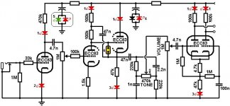
Re Lampie519 - I like it. What is it? What's it sound like? Can it be made in the 17 - 35 watt output range? Or is it already there.
If you took off all the power supply components as drawn - and put those on a separate page, that would leave room for multiple ways you could generate +350, 250, 150 and -33V DC. Very cool looking circuit - a tube op-amp that can only output AC.
If you took off all the power supply components as drawn - and put those on a separate page, that would leave room for multiple ways you could generate +350, 250, 150 and -33V DC. Very cool looking circuit - a tube op-amp that can only output AC.
Last edited:
As to the Zener amp, post # 223 my question is how much noise? The balance control is required to make that amp work.
As to the multi tube amp, post # 225, it is dangerous to both output transformers, and dangerous to loudspeakers (especially tweeters) to switch the B+ to the output stage like that. And why does it take 10 triodes to get 10 Watts?
Both amps schematics look cute. But I wonder if anybody has recently built either.
DC coupling just for the purposes of DC coupling and eliminating capacitors, sometimes causes more problems than it corrects.
Last edited:
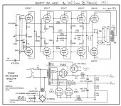
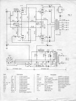
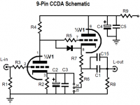
Three schematics of tube amps without coupling capacitors. The schematic with the 45's is from an article in the French magazine "Toute la Radio", March-April 1958.
Greetings,
Robert
Greetings,
Robert
Attachments
EL504,
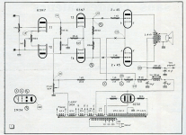
The second circuit has both grid-coupling caps and cathode bypasses. If you believe that coupling caps entail audible defects, then you must believe that cathode bypass caps do so as well. It makes no sense to eliminate one and not the other.
All the capacitor-less circuits presented so far have potentiometers connected to grids. This means grid current will flow in the wipers. This is a well known source of both noise and early potentiometer failure. Traditionally, pots not isolated from grids by capacitors was only done in the cheapest of radios, where the absolute minimum cost was the key design parameter.
If you want quality and believe eliminating all capacitors in the signal path is part of getting there, you must find some other way of providing a volume control. (professional-style switched attenuator (these require regular lubrication) ?? transformer isolated pot (ugh! any capacitor is heaps better than any transformer)? Use a light-dependent resistor (these cause distortion)??)
These are old articles and worth considering anyway. You could eliminate these caps very easy and use a current source instead (long tail) or whatever. We are not stuck on these circuits are we? Yes, "lightspeed" volume control would be possible and stepped as well. I think this is common practice now.
Thanks for sharing EL504. As Keit said, the second schematic has grid coupling caps. The third design is interesting. But it seems to run the power tube with high current, and must likely will dissipate quite some heat. For reference, here is the Acrosound 20 design. As said, it has only 1 coupling cap in the input. The other are bypasses, not couplings but are indeed in the signal path. I used that design with various OT with success, UL taps from 20 to 25% work. It is a deceptively complex amp, thanks to Herbert Keroes. There are a few mods to make it run the output tubes cooler. But the result is an extremely detailed and dynamic sound, very hard to beat with a classic coupling design. It is a remarkable design.
Attachments
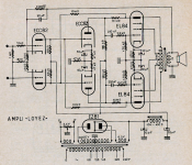
Personally i would not couple any tube DC using a resistor directly to B+ without precautions (diode or neon on the grid of the following tube). When turning on the amp all the B+ voltage will be directly available on these grids and could damage these tubes. I like followers or active current sources as these need time to become active and pass DC when all tubes are ready (heated up). Followers are even more safe as the DC is at ground level when turning on. Just good followers are more complex and more tubes are required.
Hello Brice,
Sorry about the second schematic. I did not check it good enough before posting.
The EL86's in de third schematic operate at not much more than 170 V. The cathode voltage = 165 V. With Vg1 = 150 V, the current is about 45 mA for one EL86. So without signal, the dissipation of the screen grid and the anode together is about 7,7 Watt. Pa max. of an EL86 is 12 Watt.
But i am not sure about what happens to the dissipation of the EL86's when driven hard.
Greetings,
Robert
Hello EL504.
Are you sure? I see a 65V across the 330R so a current of almost 200mA so we can assume close to 100 mA per tube, so the max for these ? I may have missed something.
Lampie, Thanks for your comment.
I never used neon or diode as protection. Can you share your knowledge on this particular case? Thank you.
Brice.
Hello Brice,
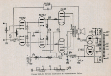
I am sure if i only look at the voltages around the EL86's and the Philips datasheet (see page 5). So if the voltages in the schematic are correct, than about 45 mA anode current and about 2 mA screen current will run per EL86. So the two EL86's draw about 94 mA.
But looking at the voltages over the resistors between B+ and ground, like you did, there must be something wrong indeed.
In the text i downloaded together with the schematic of the amp, there is mention of a total cathode current of the EL86's of 170 mA and that corresponds with your calculation.
I draw a schematic of the situation. If i have calculated the currents over the resistors between B+ and ground correctly, than there must be something wrong in the schematic of the amplifier. It is not possible that there is 197 mA running through the 330 Ohm resistor while at the same time there is only 179 mA running through the 560 Ohm resistor.
Greetings,
Robert
Attachments
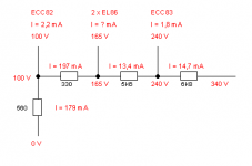
Please do not use the 560Ohm resistor but use the 100V as reference instead.
"Valvewizard" has an article about DC protection:
"a neon lamp used as grid-to-cathode arc protection on a DC-coupled stage"
The Valve Wizard -Cathode Follower
"Valvewizard" has an article about DC protection:
"a neon lamp used as grid-to-cathode arc protection on a DC-coupled stage"
The Valve Wizard -Cathode Follower
Attachments
In the circuit posted by Lampie519, the grid of the ECC83 is not in any danger. The resistors between the grid/cathode and HT total 247 kohm, limiting initial current to less than 1 mA, which is unlikely to sustain an arc. The neon seems unnecessary.
However, tube datasheets do not give ratings for allowed voltages when cathode is cold. Back in the tube era, those of us who were electronics factory engineers contemplating circuits that stress tubes in unusual ways could ask the tube factory if its ok. The answer would come back straight away, or perhaps in a week or 2 if they felt they should run tests. There's no factory engineers to call now, so we need to be more conservative.
One thing I don't like is the use of LEDs in this circuit, presumably to warn against excessive ripple from power supply electrolytic failure. If the diode that is in parallel with one of the LEDS fail into a short, the LED cannot work, and you'll never know. If the diodes fail open, the LED will go straight to LED heaven and you still won't know. One would need to ensure that HT ramp-up is slow enough that the two LEDS monitoring the input stage HT won't get blown by the initial transient. Any tube flashover will destroy the LEDs and, again, you won't know they've gone. Using a LED as cathode bias on its own is not a good idea either. At least put a capacitor across it.
Last edited:
This is not my design, i just provided a source for a neon protection as requested. The rest is of no interest for us now.
Please do not calculate the current when all tubes are warm and stable. This protection is only required when powering up and more important when replacing a tube. In this case some tubes are conducting and others not. Then you are happy you have the tubes protected. I have had many tube failures (direct coupled phase inverters mainly) as a result of a missing protection.
Please do not calculate the current when all tubes are warm and stable. This protection is only required when powering up and more important when replacing a tube. In this case some tubes are conducting and others not. Then you are happy you have the tubes protected. I have had many tube failures (direct coupled phase inverters mainly) as a result of a missing protection.
We realized that.This is not my design, i just provided a source for a neon protection as requested.
This protection is only required when powering up and more important when replacing a tube. In this case some tubes are conducting and others not.
No, as the limiting resistance is 247kohm, in both switch-on and tube changing, tube arcing is quite unlikely. However, this may not be so if a power tube is being driven - in this case the limiting resistance is likely to be much lower. Direct coupled tube circuits used to be very common in oscilloscopes and other sorts of non-audio electronics. You never found neons used in this way in such circuits.
Last edited:
- Status
- This old topic is closed. If you want to reopen this topic, contact a moderator using the "Report Post" button.
- Home
- Amplifiers
- Tubes / Valves
- A Tube amp without coupling capacitors? Possible?