But they didn't say that. If they meant different circumstances they should have said so. You're just making an unlikely assumption to suit your argument. Meanwhile it seems quite a coincidence that the graph actually matches what you would get if you put the specified 75 henries across the output of an ECC99. And it's standard to quote primary side inductance with the rated conditions - in this case 25 mA bias and signal comfortably inside the saturation limit. So, if low level response is not as good as high level as you claim (actually, the difference is typically not very significant), then a 6 Hz cutoff is the best you can hope for under any operating conditions, with an ECC99 driver.
Saturation: That reminds me - saturation is quoted as 140V pk-pk at 20Hz and 100V @ 15 Hz. That translates to saturation at ~40 V pk-pk at 6 Hz, and ~20 V pk-pk at 3 Hz. A 300B requires ~100 V grid swing - so you are not going to get full bandwidth at other than low level anyway. Even at 15 Hz, things are going to be pretty distorted. Overdriven transformers don't clip with flat or flatish tops like tubes. They tend to generate horrible spikes, as inductance rapidly collapses as saturation is approached.
In an important sense, you have bass bandwidth you can't use.
For reproduction off LP records, the only thing much below 50 Hz is turntable rumble, so no big deal perhaps. But with CD's, you get signal down to 15 Hz, so this transformer is not good at all.
Who knows doesn't need explanations and who buys or asks them will be told. Nice guy there.
What's the point of getting full drive below 15-20Hz? Most output transformer are not able to do that as well and actually give up earlier unless one uses a disproportionate transformer for a given application.
In general it is just a waste....I disagree with your analysis. There is little to nothing below 30Hz unless you listen to garbage stuff....
Last edited:
What is funny, I could not find such people among real audiophiles who used to own many different very expensive setups. They want better sound, believe own ears, and do not care about what components are in their amps. Who believes in such BS, are wannabe audiophiles who never owned audiophile quality systems. ....
You do get people who own crap that like it, and defend it to the death. Here's why:-
a) They think distorted sound is good sound, due to lack of experience. The classic demonstration of this was the 1950's introduction of FM radio in Britain. Husbands went out and bought the new FM radios and the marketing and the BBC promoted the low receiver distortion and wideband sound. Housewives hated it. To the 1950's housewife, who had typically never heard a radio reproduce better than 5 kHz, all that nice treble sounded to them like distortion - "That new wireless my husband bought doesn't have the lovely mellow tone yours does." These days, females won't listen to AM - too muddy.
b) the "Beetle Effect" - well known to those of us who have been involved in audio professionally and studied at length by psychologists. This is the phenomena of human nature that after you have spent a lot of money or done a lot of work to build something, the mind, not fully consciously, can go to extreme lengths to justify it.
It is called "Beetle Effect" after the post-war introduction of the rear-engined Volkswagen car, known as the Beetle. "Ugly cute", it was a shockingly bad vehicle - an engine that overheated (you could nearly always pick a VW coming down a hill by the popping and banging caused by burnt and leaking exhaust valves), peddles that hinged from below and not from above, and a gear linkage that made it uncertain what gear you were selecting; 6 V electrics and cheap wiring that made the headlights unevenly dim, rear wheels that occasionally sheared off, and many other faults.
But VW owners swore by them, with various silly arguments.
Oh, right. The case of the secret magic stuff known only to the favored few, and not explainable by logical analysis...Who knows doesn't need explanations and who buys or asks them will be told. Nice guy there.
Exactly - there is no point. You can't hear it. But, as I have shown, this transformer will cause serious distortion on drive above 15 Hz, and the claim it goes down to 3 Hz or even 6Hz is a false claim.What's the point of getting full drive below 15-20Hz?
CD's can go down to 15 Hz.There is little to nothing below 30Hz unless you listen to garbage stuff....
Of course, if you have an output transformer that does handle full power down to 15 Hz - such things are expensive, but not unusual - and negative feedback is employed over 2 or more stages, then the coupling over those stages must have a bandwidth down to at least one-fifth, ie 3 Hz, or the amp will be unstable and may even motorboat. Caps can do that easily, though care should be taken to avoid grid blocking (eg by limiting the driver swing), but transformers cannot.
Ceramics
In answer to the question on ceramic caps.
The low value ones are fine. These are usually COG/NPO dielectric and have good tolerance. There are larger value ones that can be made from X7R or worse Y5V dielectric. The capacitance of these drops as you apply more voltage.
I built a mic amp with ceramic input coupling caps. When the phantom power was applied (48V accross them) they became very micro-phonic so much so you hear yourself. Swapping them for polypropylene completely solved the problem but they are bigger.
So yes I would avoid ceramic coupling caps as they are likely to 22nF-1uF range. They may not have the same capacitance when DC is applied, but worse still when you are at the LF corner frequency there will be some AC across them, This will cause the capacitance to change and introduce distortion into the audio.
Temperature and Voltage Variation of Ceramic Capacitors, or Why Your 4.7mF Capacitor Becomes a 0.33mF Capacitor - Tutorial - Maxim
Last edited:
You do get people who own crap that like it, and defend it to the death. Here's why:-
a) They think distorted sound is good sound, due to lack of experience. The classic demonstration of this was the 1950's introduction of FM radio in Britain. Husbands went out and bought the new FM radios and the marketing and the BBC promoted the low receiver distortion and wideband sound. Housewives hated it. To the 1950's housewife, who had typically never heard a radio reproduce better than 5 kHz, all that nice treble sounded to them like distortion - "That new wireless my husband bought doesn't have the lovely mellow tone yours does." These days, females won't listen to AM - too muddy.
b) the "Beetle Effect" - well known to those of us who have been involved in audio professionally and studied at length by psychologists. This is the phenomena of human nature that after you have spent a lot of money or done a lot of work to build something, the mind, not fully consciously, can go to extreme lengths to justify it.
It is called "Beetle Effect" after the post-war introduction of the rear-engined Volkswagen car, known as the Beetle. "Ugly cute", it was a shockingly bad vehicle - an engine that overheated (you could nearly always pick a VW coming down a hill by the popping and banging caused by burnt and leaking exhaust valves), peddles that hinged from below and not from above, and a gear linkage that made it uncertain what gear you were selecting; 6 V electrics and cheap wiring that made the headlights unevenly dim, rear wheels that occasionally sheared off, and many other faults.
But VW owners swore by them, with various silly arguments.
Oh, right. The case of the secret magic stuff known only to the favored few, and not explainable by logical analysis...
Exactly - there is no point. You can't hear it. But, as I have shown, this transformer will cause serious distortion on drive above 15 Hz, and the claim it goes down to 3 Hz or even 6Hz is a false claim.
CD's can go down to 15 Hz.
Of course, if you have an output transformer that does handle full power down to 15 Hz - such things are expensive, but not unusual - and negative feedback is employed over 2 or more stages, then the coupling over those stages must have a bandwidth down to at least one-fifth, ie 3 Hz, or the amp will be unstable and may even motorboat. Caps can do that easily, though care should be taken to avoid grid blocking (eg by limiting the driver swing), but transformers cannot.
You are a talker. Go on....LOL
Last edited:
I once made a circuit by Audio Research, preamp, with a negative bias and ECC82.
Two stages with a coupling cap in between. Then DC feedback - no cap in the feedback path; then you might say that the negative power rail cap is in between. Just about 20dB feedback overall, so not too much. I tested without an output cap - only the scope input cap") .
.
I tried a lot of different coupling caps, and these all differed in BW and ringing. Just a few I had in my stock were smooth.
Of course I didn't document it for sharing (being a bricoleur, too bad).
Later I made something similar with one cap too, now no negative rail, and now DC coupling in between, just an output cap this time, and feedback across that cap from the output. And I saw the same but more erratic HF - I also noted slew rate effects this time, and sharper resonances but I think I liked the PIO here on the bench. This second preamp was too bright to my liking in the living room.
Probably I am hyper testing with situations that do not occur in real life.
Currently I have just bought a 10K:10K split output (for 25mA). We'll see how it performs when I apply the rakes. On paper (LTSpice) it looks good so far, SE has higher bandwidth (300kHz against 110 kHz) while the PP sometimes shows a sharp peak above 500 kHz; SE goes lower 3 against 5 Hz (but that is of no concern). The peak worries me. I will do the SE. I will use the option of 10K:2K5.
What I am looking for is a reasonable amount of 2nd harmonics - I had a preamp based on 6J6 in, DC coupling, E90CC out, two rails +/- 150 Volts, 1% second harmonics and it was great. [But I dropped after 15 years it because the input tubes were mechanically ringing when I turned the stepped att, sloppy grid wires ] But it is this smooth sound I am looking for again.
If this 6SN7/transformer is no good to give stable 2nd harmonics, I will test a 2SJ28 SIT device I treated myself on as preamp.
Two stages with a coupling cap in between. Then DC feedback - no cap in the feedback path; then you might say that the negative power rail cap is in between. Just about 20dB feedback overall, so not too much. I tested without an output cap - only the scope input cap
.I tried a lot of different coupling caps, and these all differed in BW and ringing. Just a few I had in my stock were smooth.
Of course I didn't document it for sharing (being a bricoleur, too bad).
Later I made something similar with one cap too, now no negative rail, and now DC coupling in between, just an output cap this time, and feedback across that cap from the output. And I saw the same but more erratic HF - I also noted slew rate effects this time, and sharper resonances but I think I liked the PIO here on the bench. This second preamp was too bright to my liking in the living room.
Probably I am hyper testing with situations that do not occur in real life.
Currently I have just bought a 10K:10K split output (for 25mA). We'll see how it performs when I apply the rakes. On paper (LTSpice) it looks good so far, SE has higher bandwidth (300kHz against 110 kHz) while the PP sometimes shows a sharp peak above 500 kHz; SE goes lower 3 against 5 Hz (but that is of no concern). The peak worries me. I will do the SE. I will use the option of 10K:2K5.
What I am looking for is a reasonable amount of 2nd harmonics - I had a preamp based on 6J6 in, DC coupling, E90CC out, two rails +/- 150 Volts, 1% second harmonics and it was great. [But I dropped after 15 years it because the input tubes were mechanically ringing when I turned the stepped att, sloppy grid wires
] But it is this smooth sound I am looking for again.If this 6SN7/transformer is no good to give stable 2nd harmonics, I will test a 2SJ28 SIT device I treated myself on as preamp.
Last edited:
People say all sorts of things. Not all of them are true.jjasniew said:Some say the cap (and its character) is an integral part of the tube sound and if you take that away, you'll lose a part of "our sweet vacuum tubes" sound.
When RC coupling is done properly and appropriately you will not hear it.Since I'm pretty sure I've only heard any tube amp with RC coupling, I wouldnt know any different.
I'm not sure whether you are talking of the sound of any competent amp using any technology (including tubes) or whether you are talking of the small distortion from the tubes and the minor bandwidth limitation imposed by the OPT - both most noticeable in feedback-less amps favoured by those not seeking high fidelity sound reproduction."sweet musical vacuum tube" sound
A cap with a significantly nonlinear dielectric would sound different with DC bias because the dominant 3rd with no bias becomes dominant 2nd with bias. Such caps would not normally be used for coupling audio.I also realize that caps will sound different with a DC bias (er, class A?), versus conducting an AC signal through.
People often claim that DC servos are not in the signal path, and so no caps are in the signal path. They are wrong. A DC servo for a solid-state amp gains a small advantage by replacing an electrolytic (clearly in the signal path, typically in the feedback) with a smaller value film cap (superficially not in the signal path, in the servo loop - which is part of the feedback, so clearly in the signal path) which may be more linear than the electrolytic. A simpler solution is to make the electrolytic bigger.I have to believe that if "auto-biasing" is practical, even no problem, then any balance drifting issues when using DC coupling - with warm-up, component ageing, AC line variations etc - could be taken care of by some "auto balancing" circuit that's NOT IN THE SIGNAL PATH IN ANY WAY (I like that all-caps claim).
//off//
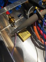
Someone had questions about 1MHz insterstage transformers capability.
Here are frequency response measurements of one of mines with a 1:1 ratio
Core AMCC50
It IS NOT bifiliar.
-5dB at 1MHz with a 2k driving impedance.
For Single ended stages. Can be rewired for PP to PP
Gap adjusted for 80H, 20mA

Someone had questions about 1MHz insterstage transformers capability.
Here are frequency response measurements of one of mines with a 1:1 ratio
Core AMCC50
It IS NOT bifiliar.
-5dB at 1MHz with a 2k driving impedance.
For Single ended stages. Can be rewired for PP to PP
Gap adjusted for 80H, 20mA
Its fairly straightforward to level shift using a zener diode, and you can use gas regulator tubes in place of a zener if you distrust silicon. You won't get the best noise performance unless you decouple the zener/gas tube...
By the way valve opamps do exist, and are exactly a DC coupled differential amplifier driving a VAS and output stage. Google K2W, K2X, Philbrick.
By the way valve opamps do exist, and are exactly a DC coupled differential amplifier driving a VAS and output stage. Google K2W, K2X, Philbrick.
The NE2s used in the Philbrick & other toob Op Amps were selected for low noise & stability. But to build a DC coupled amp zeners or NE2s are not required to be in the signal path. Depending on the -ve supply available, the signal loss due to the R dividers necessary can be kept to a minimum.
DC coupled amps are not a big deal at all, well known in industry for a very long time. Need both +ve & -ve power supplies, preferably regulated.
DC coupled amps are not a big deal at all, well known in industry for a very long time. Need both +ve & -ve power supplies, preferably regulated.
One thing I haven't heard mentioned is the common mode signal in P-P. An interstage xfmr would eliminate that, while cap coupling would not, unless followed by a CCS tail differential stage. Any amplifying stage with distorting devices generates some common mode signal, passed on to the next stage.
While the common mode signal would nominally cancel out in the output/OT stage (for class A only), it would still affect the distortion profile of the output tubes by changing their operating point. Maybe this is what leads to so called sound differences between xfmr and cap coupling.
DC coupled would suffer from common mode effects obviously too. Some SS Op Amps have a common mode nulling servo loop.
Last edited:
Maybe you are too old to find it.
Probably true, but "in my day" there was no need to look for great music. It was everywhere. Musicians could read music and played real instruments. Songs had more than 10 words, they had melody, and they sang about others things besides sex. Musicians had a lot more brains and a lot less testosterone.
Probably true, but "in my day" there was no need to look for great music. It was everywhere. Musicians could read music and played real instruments. Songs had more than 10 words, they had melody, and they sang about others things besides sex. Musicians had a lot more brains and a lot less testosterone.
"Those were the days..."
Musicians can still play instruments and read music. "Great" music is subjective, and lyrics in music are unnecessary IMHO. The best music is instrumental (even if it's electronic).
Glen Miller and Artie Shaw are good examples of great band leaders that didn't need a bunch of words to make their music appealing. These days, I mainly listen to Drum and Bass, Liquid, Drumstep etc, but I still love my Jazz and even some classical like Elgar.
//off//
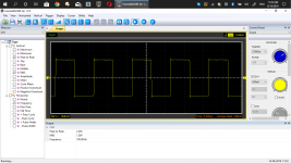
Someone had questions about 1MHz insterstage transformers capability.
Here are frequency response measurements of one of mines with a 1:1 ratio
Core AMCC50
It IS NOT bifiliar.
-5dB at 1MHz with a 2k driving impedance.
For Single ended stages. Can be rewired for PP to PP
Gap adjusted for 80H, 20mA
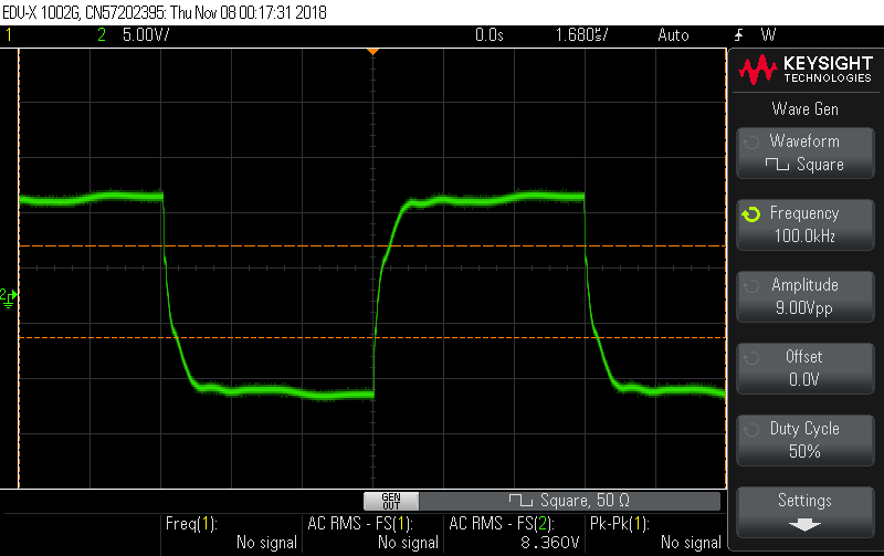
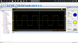
Interesting scope trace for 100kHz through an IT.
Here's my scope trace of 100kHz through a Carli 1uF X2 MKP safety capacitor which I use for coupling.
Also included is a trace at 1MHz.
Not bad for a 50 cent capacitor...
Attachments
DC coupled would suffer from common mode effects obviously too. Some SS Op Amps have a common mode nulling servo loop.[/QUOTE]
That is possible in a toob diff amp as well. 1st diff stage has an active tail, say a triode. The Common Mode signal on the cathodes of the 2nd stage is fed back to the grid of the first stage tail. Common mode reduction depends on the fraction fed back & gain of the tail tube.
Depending on the supply voltages a large CM Tolerance is also possible.
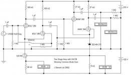
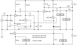
Active CM NFB
Here is a 2-stage diff amp with that cct I referenced. It is NOT DC coupled, but can easily be done. While doing the search I found e few example of DC coupling but not with the active CM NFB.
Stuffing the numbers into the HP67 & turning the crank I see a little better than 70 db CMR. In a practical cct would not be as good, real toobs, resisters & so on are never perfect.
Attachments
//off//
Someone had questions about 1MHz insterstage transformers capability.
Here are frequency response measurements of one of mines with a 1:1 ratio
Core AMCC50
It IS NOT bifiliar.
-5dB at 1MHz with a 2k driving impedance.
For Single ended stages. Can be rewired for PP to PP
In bifilar 1:1 transformers coupling is not inductive. It is inductive AND capacitive. You are getting 1 MHz through a capacitance between primary and secondary.
- Status
- This old topic is closed. If you want to reopen this topic, contact a moderator using the "Report Post" button.
- Home
- Amplifiers
- Tubes / Valves
- A Tube amp without coupling capacitors? Possible?