Ok, I'm going to pull my intellectual pants down and reveal my ignorance for all to see.
"How come they dont" make a tube amplifier, say push pull, DC coupled all the way through, like an IC op-amp is.
It seems way back when Mr Philbrick made an op-amp module using 12AX7s no less and it seems from my limited research the idea of using tubes as DC coupled amplification was never developed out. Certainly not like analogs ICs Have over the past 40 -
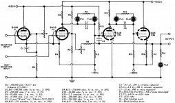
The problem of ridding the circuit of all DC blocking capacitors come down to what else would you use to block the DC? That voltage bias the audio is riding upon from the preceding stage? The only thing I was able to dig up on this is illustrated in the schematic below;
They use a couple of NE-2s to make a floating, 2 pin voltage drop that allows the interstage coupling to land the next stage's grid bias right where it needs to be. I assume that's the only way it could actually work. The pf value capacitor across the Neons suppresses noise, would be my guess?
C'mon. You mean to tell me in all of designing and construction of modern day tube amplification no one has done better than a couple of NE2s as a realizable solution? The Capacitor is just so easy to use! I would think there'd be all kinds of tube based voltage drop circuits, where all some tubes in the amp do is drop voltage between amplification stages.
The reason I'm targeting these capacitors is, IMHO, that the whole music system from the D/A converter output buffer on out is "Capacitor Soup". The audio output from the chip sits up at some positive voltage, so a capacitor is used to block it. That's #1 and I'll save you all by not going through all of 'em to the speaker voicecoils.
Any capacitor that has current going in and out of it in response to music being played through an amplifier / speaker system is imparting its flavor into the recipe. So we have all the high end capacitor products and a lot of knowledge about the various types that sound good. I've always admired how they get rid of one between the input gain stage and the cathodyne...
Does anyone know if such a thing as a non-capacitive coupled tube amp has ever been designed? I mean, the more than two tubes per channel kind. I realize it's a lot more expensive, as such circuits perhaps require regulated and an additional negative supply. But is there a technical (vs financial) reason why this is "never done"?
Let's say an answer is something like "You'd have to have separate, isolated filament windings for all those tubes". So? More glow...
Realizing it's bad to put a DC bias on the output transformer, perhaps being DC coupled all the way through to the output transformer primary isnt so good as well. But, could it be managed reasonably ; instead of blocking a DC offset, detect it like a speaker protection circuit does in a SS amp. Thanks for any discussion on this.
"How come they dont" make a tube amplifier, say push pull, DC coupled all the way through, like an IC op-amp is.
It seems way back when Mr Philbrick made an op-amp module using 12AX7s no less and it seems from my limited research the idea of using tubes as DC coupled amplification was never developed out. Certainly not like analogs ICs Have over the past 40 -
The problem of ridding the circuit of all DC blocking capacitors come down to what else would you use to block the DC? That voltage bias the audio is riding upon from the preceding stage? The only thing I was able to dig up on this is illustrated in the schematic below;
They use a couple of NE-2s to make a floating, 2 pin voltage drop that allows the interstage coupling to land the next stage's grid bias right where it needs to be. I assume that's the only way it could actually work. The pf value capacitor across the Neons suppresses noise, would be my guess?
C'mon. You mean to tell me in all of designing and construction of modern day tube amplification no one has done better than a couple of NE2s as a realizable solution? The Capacitor is just so easy to use! I would think there'd be all kinds of tube based voltage drop circuits, where all some tubes in the amp do is drop voltage between amplification stages.
The reason I'm targeting these capacitors is, IMHO, that the whole music system from the D/A converter output buffer on out is "Capacitor Soup". The audio output from the chip sits up at some positive voltage, so a capacitor is used to block it. That's #1 and I'll save you all by not going through all of 'em to the speaker voicecoils.
Any capacitor that has current going in and out of it in response to music being played through an amplifier / speaker system is imparting its flavor into the recipe. So we have all the high end capacitor products and a lot of knowledge about the various types that sound good. I've always admired how they get rid of one between the input gain stage and the cathodyne...
Does anyone know if such a thing as a non-capacitive coupled tube amp has ever been designed? I mean, the more than two tubes per channel kind. I realize it's a lot more expensive, as such circuits perhaps require regulated and an additional negative supply. But is there a technical (vs financial) reason why this is "never done"?
Let's say an answer is something like "You'd have to have separate, isolated filament windings for all those tubes". So? More glow...
Realizing it's bad to put a DC bias on the output transformer, perhaps being DC coupled all the way through to the output transformer primary isnt so good as well. But, could it be managed reasonably ; instead of blocking a DC offset, detect it like a speaker protection circuit does in a SS amp. Thanks for any discussion on this.
Attachments
Last edited:
Does anyone know if such a thing as a non-capacitive coupled tube amp has ever been designed?
Agree with your statements. And I like the grid biasing this design has.
Alternate design idea: [ I am just designing an amp where the cathode of a cathode follower 'bleeds' some singal out of phase to the driver cathode - it is out of phase and can totally cancel the signal there, better in bandwidth than an electrolytic can do. And after some handling you can get the DC right too. Some also used this to get some positive feedback - that increases dynamics, by changing the relationship of that balancing. I can get a 1 dB 'boost' that way without a cathode capacitor compared to having it in place. This is slow, the simulation works slower than the lab bench.]
There are many transformer coupled amplifiers. This is what Western Electric generally had in their famous professional equipment.
And several amplifiers used amplifiers where the anode DC of one stage mathes the cathode DC of the next stage. See for instance the Loftin-White designs.
By the way. I also once saw an amplifier that also had NO power supply electrolytics. [Not too hard, it had a shunt power stabilizer and an series choke input. And a rather high tension to start with].
Last edited:
There's lots of ways to design a tube amp without coupling capacitors. The Loftin-White configuration goes back to the early 1930's.
Probably the best way is to have a negative power rail, and couple a preceding anode to the next grid with a resistive divider between anode and negative rail. This lets you bias the grid correctly and only loose a few db of signal. You need an interlock in the power supply, otherwise failure of the negative rail will write off the output tubes.
The trouble is, all the non-cap configurations have severe disadvantages: multiple power rails needed, gas tubes (noisy, short life), and low efficiency, or interstage transformers, which cost money and stuff up the sound. And unless you have high-z loudspeakers, you must have an output transformer. The o/p transformer is always the weakest link in a competently designed amp, not the capacitors. Transformer problems limit the amount of negative feedback that can be used, so operating conditions with direct coupling are not stable. Slight changes in emission in input tubes cause big shifts in output tube conditions. In fact tube manufactures all recommended against DC coupling except for applications (such as analog computers) for which there is no alternative.
You can solve the DC drift problem to a certain extent by going fully differential from input to output. But worsens the signal to noise ratio by 3 dB, and noise is already a problem with tubes in audio.
No power supply electrolytic designs were once common in high grade professional equipment, as early electros didn't last long and had a high failure rate. Nothing remarkable about it.
With one or more chokes in the power supply, tube amps need only a few microfarads, making block oil-filled paper capacitors practical, though too expensive for consumer equipment.
Probably the best way is to have a negative power rail, and couple a preceding anode to the next grid with a resistive divider between anode and negative rail. This lets you bias the grid correctly and only loose a few db of signal. You need an interlock in the power supply, otherwise failure of the negative rail will write off the output tubes.
The trouble is, all the non-cap configurations have severe disadvantages: multiple power rails needed, gas tubes (noisy, short life), and low efficiency, or interstage transformers, which cost money and stuff up the sound. And unless you have high-z loudspeakers, you must have an output transformer. The o/p transformer is always the weakest link in a competently designed amp, not the capacitors. Transformer problems limit the amount of negative feedback that can be used, so operating conditions with direct coupling are not stable. Slight changes in emission in input tubes cause big shifts in output tube conditions. In fact tube manufactures all recommended against DC coupling except for applications (such as analog computers) for which there is no alternative.
You can solve the DC drift problem to a certain extent by going fully differential from input to output. But worsens the signal to noise ratio by 3 dB, and noise is already a problem with tubes in audio.
By the way. I also once saw an amplifier that also had NO power supply electrolytics. [Not too hard, it had a shunt power stabilizer and an series choke input. And a rather high tension to start with].
No power supply electrolytic designs were once common in high grade professional equipment, as early electros didn't last long and had a high failure rate. Nothing remarkable about it.
With one or more chokes in the power supply, tube amps need only a few microfarads, making block oil-filled paper capacitors practical, though too expensive for consumer equipment.
The reason I'm targeting these capacitors is, IMHO, that the whole music system from the D/A converter output buffer on out is "Capacitor Soup"...
Any capacitor that has current going in and out of it in response to music being played through an amplifier / speaker system is imparting its flavor into the recipe. So we have all the high end capacitor products and a lot of knowledge about the various types that sound good.
Seems to me that you are starting from a position that is not necessarily grounded in fact. There are a lot of myths and marketing hype around caps no matter where they are located and what they are doing in a design - not the least of which is that a particular brand of capacitor might be relied on to "sound good".
In very simple terms, a capacitor in the signal path does a very simple job. In blocks DC voltages and passes AC signals. A well-made capacitor (regardless of the name on the wrapper) will do this predictably and consistently following well-understood laws of physics. Any tonal qualities it injects to the signal are the result of interaction with other circuit components, not an inherent quality of the cap itself.
Having one less component is an admirable goal in any circuit and there are plenty of options for reducing the capacitor headcount in a design. Unfortunately, they tend to involve increased complexity or cost or both.

No. You have been reading too many audio websites and reading too few electronics textbooks.jjasniew said:Any capacitor that has current going in and out of it in response to music being played through an amplifier / speaker system is imparting its flavor into the recipe.
If you want to improve a tube amp then the first thing to get rid of is the tubes. Then ditch the transformers. After that it is difficult to decide whether to get rid of the resistors or capacitors - maybe the caps should go. Finally, some would want to get rid of the wires.
The reason you don't see tube circuits wired like modern opamps is that nobody has invented opposite polarity tubes using positrons instead of electrons.
I once built a three stage fully differential push pull amplifier that had no capacitors in the signal path. It worked, and sounded nice but DC offsets are the deal breaker. As tubes age, the line voltage changes, or even the room temperature changes, the DC offset in the input stage may shift by a few millivolts. This is not a problem when there are capacitors in the path, but a DC coupled amp will be horribly out of balance at the output stage from a minor shift in the input stage. I had to adjust the bias on that amp every time I turned it on, and often during use in the summer when our line voltage varied by several volts on a hot day.
I became convinced that no more than two stages should be DC coupled, and the total gain of those two should be just the minimum needed for the task.
Some of the common DC coupled single ended circuits found on the web still have a big fat electrolytic cap in the power supply. This cap IS in the signal path on a single ended amp. I's is also in the path on a P-P amp, but is not as important due to the cancellation of many common mode effects.
Agree with DF96:
"No. You have been reading too many audio websites and reading too few electronics textbooks.
If you want to improve a tube amp then the first thing to get rid of is the tubes. Then ditch the transformers. After that it is difficult to decide whether to get rid of the resistors or capacitors - maybe the caps should go. Finally, some would want to get rid of the wires.
The reason you don't see tube circuits wired like modern opamps is that nobody has invented opposite polarity tubes using positrons instead of electrons."
Transformers have far worse characteristics than any decent cap used well within its design limits. Why the love of those and distaste for caps???
My findings are pretty much in line with tubelab's comments, when I was still designing and building PP amps I used dc coupled driver stages which I capacitively coupled to the output stage. Optimizing performance for the available supply voltages and building in tolerance for drift and line voltage variations was quite the task.
As DF96 states, the reason you see comparatively few fully dc coupled designed is the lack of a complementary device and substantially more complex design and power supplies. Have a look at a vintage Tektronix scope vertical amplifier design for examples of a "fully developed" DC coupled amplifier design.
Acrosound also had a PP 6BQ5 which was DC coupled which is noted both for its unreliability and propensity for eating output tubes.


Built this a few years ago. It's my headphone amp now.
https://www.diyaudio.com/forums/att...-white-801-amp-801loftin-white-sn7-schema-gif
https://www.diyaudio.com/forums/att...-white-801-amp-801loftin-white-sn7-schema-gif
If the definition of "tube amp" includes headphone amps then it's actually easy (except for any large value capacitors in the power supply, of course). The recipe for a single-ended, single-tube headphone amp is simplicity itself:
1) Use an output transformer with about 5k to 10k primary impedance and a secondary impedance that is close to the impedance of your headphones (something like a 50 ohm secondary would work for most).
2) Use a high transconductance, frame grid RF pentode that will have a gain of at least 30 and plate resistance of about 1000 ohms when wired triode. Wire it triode. 12GN7A or 6e5P would work.
3) Use paralleled LEDs to cathode bias the tube. (I ended up preferring the sound of a cathode resistor with bypass capacitor, but maybe I actually like bad 'capacitor sound'.)
4) Regulate the plate supply. Something like 150V to 200V DC that can deliver 100mA or so should work for a stereo amp. (I wound up getting lazy; after trying mine with a choke input passive power supply with RC decoupling I ended up keeping it that way because it's dead quiet and sounds good to me. It even has AC heaters, but I can't hear any hum at all.)
That's a single-stage, single-ended triode, output transformer coupled headphone amp with no coupling capacitors.
--
- Status
- This old topic is closed. If you want to reopen this topic, contact a moderator using the "Report Post" button.
- Home
- Amplifiers
- Tubes / Valves
- A Tube amp without coupling capacitors? Possible?