Most worry about a parallel RC network: cathode resistor and capacitor in parallel; while actually capacitor plus internal series resistance/impedance is way more important.
Rk or RC is trivial, do you really think a 100uf or 150uf , f3 at -5hz or 1hz would make a difference? I don't.
The worst that can happen is that the capacitor value is higher than required by like 50%, it is not the end of the world.
Academia, this is interesting, auto bias ok, how do you know that the OT has the maximum inductance at this 'adjustment'?
Answer: you have no clue
we do balance the currents in the OT to obtain 2n order reduction of harmonics and most important to reduce the resultant currant which eats your transformer power.
Try an Edcor (the best ones) and an audionote, take a lundhal, take a toroidal.
Measure the THD at 20hz while you adjust the bias, you will see that the inductance has the biggest effect on the sound quality.
If the magnetic fields are not equal at equal bias, you need to change it a bit.
Then the 2n harmonics are not cancel perfectly right? So you unbalance slightly the drivers to compensate and get the best of both worlds. This is very advanced.
PL uses perfectly perfect symmetrical (balanced) OTs made in the USA according to the specifications. required by the manufacturer. They are not toroidal, that seems to me to be a comparison of the style "pears with apples."
The adjustment of the PL autobias is based on the determination of a working point of the polarization curve of each tube individually so that it does not work to the limit and thus extend its useful life, in addition to working in a zone of less distortion. It is not a simple resistance polarization as other brands use.
The harmonics of any order (first, second, etc.) are present in all amplifiers (Audio Note, CJ, Jadis, etc.) with PP output, because they are the necessary and essential previous step for the adaptation of impedances between the output valves and the windings of the transducers. If there is influence of "unbalanced inductances there, it applies to all tube amplifiers with conventional OT output.
The audio signal is not affected by the autobías, until it reaches the end of its path, there it is influenced only in the output like any other amplifier with OT. That has nothing to do with the comfort of living unconcerned with bias adjustments due to valve changes (not all amplifiers allow you to use a KT-66 or a KT-150 without cumbersome complications) and the auto bias allows comparison at the moment of different types of tubes, but it is not a simple tube rolling, (although it is not good to abuse it because false contacts can occur in the sockets of both "remove and put") I have put two EL-34 in a channel and two KT-88 in the other and just by balancing from a preamp assess the sound of them. It was a nice experience, I recommend it to anyone who can access a PL with cars.
And no, I will not be able to listen to the Audio Note, CJ, Manley, etc, etc, because they are in "other leagues", (of prices) and those brands do not abound here.
Although I cannot technically comment on specific details that I do not master at the "specialist" level, I only speak of my experience with PL autobias. and how satisfied I am with my acquisition.
And I repeat that it is excellent, and although many want to discredit it, for a "common" user, it is a highly recommended step to enter the world of valve sound. In addition, I have noticed that those same developments of autobias are being incorporated into some "classic" amps. Check out what they developed for Dynaco, for example.
audioamp.eu
Discover our latest solutions for output stages of tube amplifiers !
This website focuses on tube amplifier solution using modern elements. Special attention is paid to amplifiers output stages- their setting and control, output transformers, power supply units and another amplifier parts.
The information is based on many years of experience in construction and measuring of tube amplifiers, development of modules for tube stage control & quality output transformers . Comparisons of various connection types, measurement results and recommendations for the construction of modern tube amplifiers are all to be presented here.
You can easily equip your existing tube amplifier with fully analogous circuits that enable an effortless automatic bias control so that you can completely avoid repeated re-setting of output stages resulting from tubes aging and at the same time guarantee optimum conditions for the permanent operation of your tube amplifier.
Beautiful enjoyment of listening to music !
Silken bass, crystalline height !
Set your optimal bias for amplifier forever !
Fitting the module into your amplifier will have these benefits:
no need to constantly re-adjust tube operating points
significantly extended tube life
current regulation not influenced by the music signal
clear undistorted sound for a great listening experience
significant increase in signal clarity – extreme reduction of hum and noise level of the amplifier
improved bass transmission
no maintenance or additional setup
optimum utilization of tube life
suitable for all types of output transformers (namely toroidal transformers which require automatic control)
safe operation due to minimized danger of runaway tube current – even when the amplifier is left unattended
universal use: suitable for all connection types
fully analogous control: the module has no digital elements
The modules are suitable for all amplifier types (classes A, AB, or B), as well as single-acting amplifiers with A-class tubes connected in parallel.
Their use is strongly recommended in existing amplifiers with fixed bias of output tube control grids, as aging of the tubes causes the need for a constant re-adjustment of their operating points.
The connection secures an absolute symmetry of anode currents through both branches of primary winding of the output transformer. This way, saturation of the the output transformer core with DC current with subsequent signal distortion and dearease in available power is reliably avoided.
Furthermore, tube operating points need no further re-adjustments. The module constantly creates optimum conditions for the output stage, independently of tube aging and consequent changes in their parameters.
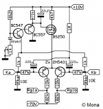
OT:
The incorporation of a CR to a valve amplifier is not very common, as far as I know, it is a great comfort to control the volume, the input selector, the switching from triode to pentode, the mute, all from your chair!
Regards
Last edited:
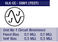
It is intended for 6L6 self bias, so no problem.it will never work, because the 330k resistance is too much.
my power tubes need 25k grid to ground maximum. I use unregulated fix bias, no issues at all and I will never ever use cathode bias.
Mona
Attachments
Ketje,
Thanks!
Oh, gosh.
For some who are trying to decide which bias to use:
Just one of the tradeoffs of using fixed bias.
The grid resistor has to be lower, so the driver has to work harder.
(one solution that has been well applied is the driver tube driving a MOSFET, which drives the output tube grid).
Self Bias has less parts, and can use a higher resistance grid resistor, making for a simpler driver circuit and less parts.
Oh, did I mention using an interstage transformer, then the only resistance is that of the transformer DCR, and resistance (across the bias V to ground).
Solutions, Solutions, . . .
Tradeoffs, Tradeoffs, . . .
Last edited:
No, the worse that can happen is that the cathode bypass capacitor is perhaps only 20% of the value it needs to be.gabdx said:Rk or RC is trivial, do you really think a 100uf or 150uf , f3 at -5hz or 1hz would make a difference? I don't.
The worst that can happen is that the capacitor value is higher than required by like 50%, it is not the end of the world.
academia50,
Wow!
The link you posted: AutoBias Adjustment — PrimaLuna USA
. . . has pictures of hands on the circuitry.
The vendor's text says not to touch any circuitry,
But a picture is worth 1000 surviving spouses.
Just sayin'
You realize it was instruction to use KT120 in an amp that came with EL34? This is why an adjustment is needed. Otherwise don't touch it. I was surprised not to see HV warnings etc.
academia50,
Wow!
The link you posted: AutoBias Adjustment — PrimaLuna USA
. . . has pictures of hands on the circuitry.
The vendor's text says not to touch any circuitry,
But a picture is worth 1000 surviving spouses.
Just sayin'
I imagine that it is for illustrative purposes, and the circuit is without power and with the filters unloaded .....
")
Oh, I repeated the same link twice, I wanted to put this one!
Thanks !
Adaptive AutoBias — PrimaLuna USA
The only adaptive autobias I found worth using long time ago, was based on S/H and envelope sensing. It was an integrator in servo, using very low input current opamp and a teflon capacitor, with MOSFET switch before it that got closed when music level was above pretty low threshold. I discarded this idea because checking and adjusting of bias once per year or even per month is enough, while S/H could not hold it long enough during playing of classical music.
However, today a microprocessor chip with ADC, memory, and DAC can be used instead. And I am pretty sure that there are people who already designed such kits and sell them.
However, today a microprocessor chip with ADC, memory, and DAC can be used instead. And I am pretty sure that there are people who already designed such kits and sell them.
I hadn't heard of autobias, but if Wikipedia is to be believed it is the same as cathode bias, also called self bias. But then this is "audiophile" stuff, where an apple could be called a banana (apologies to Alfred Kahn). A schematic would help clear things up, but that's too often considered a "trade secret," and the intended audience most likely can't read a schematic anyway.
Cathode bias - Wikipedia
On the other hand, there's this, and there may well be too much self-bias among audiophiles.
What is Self-Bias and Why is it Killing Your Career? | Inc.com
Cathode bias - Wikipedia
On the other hand, there's this, and there may well be too much self-bias among audiophiles.
What is Self-Bias and Why is it Killing Your Career? | Inc.com
Last edited:
That has to be the Sony patent !The only adaptive autobias I found worth using long time ago, was based on S/H and envelope sensing. It was an integrator in servo, using very low input current opamp and a teflon capacitor, with MOSFET switch before it that got closed when music level was above pretty low threshold.
Here is another one, if you like a puzzle
Mona
Attachments

That has to be the Sony patent !
And they patented it 20 years before I started considering tubes worth using, re-inventing the wheel!
True, but you get the benefit of self adjustment along with the lack of wasted power in a resistor
A customer so liked the benefit that he had me make him a panel with a meter and 10 position switch by which to set bias on each of his 4 PP amps, with two positions left for future.
- Status
- This old topic is closed. If you want to reopen this topic, contact a moderator using the "Report Post" button.
- Home
- Amplifiers
- Tubes / Valves
- Autobiasing output tubes (6L6)?