") My 45SE finally born today and is working good ! after 20 +? months
My 45SE finally born today and is working good ! after 20 +? months  in & out to rest on my bench.
Thanks to all you people that support me on this project. There was no chance to me to did it without your help. iT IS ON now and is sounding Great !
Special thank you to 6A3sUMMER that was support me for weeks to put it this amp in track to finish it.
Now only the constant current and bias voltage need to increase to optimal performance. Thanks for any advise to do it.
*Diagram included the actual measures.
* also any idea of right NFB value to use ?
Last edited:
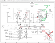
Thanks Tj226, it is probably I'm confused cause my first amp and only basic technical knowledge. This was original with 2A3 option (on corner with red cross) and was designed to ccs, the 1.6k resistor was recommended if will not add the 2a3 option. Are used now for 45 use only. The 1.6k resistors exchange the original ccs option circuit ? and no need to match the 35mA current ?
I see. The 275v maximum voltage is referring to the voltage across the tube. In other words it is the voltage measured between your cathode and the plate. If you are not trying to run your tube at 275v, then I assume you are aiming for 250v on the plate and 34ma of plate current. Here is what you should be seeing in terms of voltage in that case. Pin 2 (the tube plate) with respect to ground should be 300v. The wiper pin of your hum bucking pot should be at 50v with respect to ground. If you get those numbers or something very close, you should be fine.Thanks Tj226, it is probably I'm confused cause my first amp and only basic technical knowledge. This was original with 2A3 option (on corner with red cross) and was designed to ccs, the 1.6k resistor was recommended if will not add the 2a3 option. Are used now for 45 use only. The 1.6k resistors exchange the original ccs option circuit ? and no need to match the 35mA current ?
kkstereo,
Your 45 tubes are at 322V plate, and either 48.5 or 52.5 V filament to grid (self bias).
The maximum suggested operation for the 45 is 275V plate to filament; 36mA, and 56V bias. The maximum 45 plate dissipation is 10Watts.
First the conditions you are experiencing: (Save time and scroll down to "The solution")
322V - 48.5V = 273.5V Plate-to Filament 48.5V / 1600 Ohms = 30.3 mA 273.5V x 30.3 mA = 8.287 W plate dissipation 322V - 52.5V = 269.5V Plate-to-Filament. 52.5 / 1600 Ohms = 32.8 mA 8.839 W plate dissipation
They are not to far from the 45 operating specs above. They are about 18% to 12% lower than the 10 W max.
First, swap the 45 tubes, and see if the voltages and currents ‘move’ with the tube. If they do not move, then it means that the 1600 Ohm resistors are not equal, or the output transformer primaries DCRs are not equal (or both the resistors and the primary DCRs). If it follows as you swap the tubes, then the difference is due to the tubes, not to the 1600 and primary DCRs.
Lets look for a way to get you closer to the 45 max operating specs.
The 45 plate resistance, rp, is 1700 Ohms
275V spec - 273.5V measured = 1.5V 1.5V / 1700 Ohms = 0.8 mA Raise the B+ by 1.5V, and the current for that tube will raise by about 0.8 mA (31.1 mA). (Self bias will cause the current to raise a little less than 0.8 mA). New B+, 323.5V x 31.1 mA = 10.06W plate dissipation.
275V spec - 269.5V measured = 5.5V 5.5V / 1700 Ohms = 3.2mA Raise the B+ by 5.5V, and the current will raise by about 3.2mA (36mA). (Self bias will cause the current to raise a little less than 3.2 mA). New B+, 327.5 x 36mA = 11.79 Watts.
The Solution:
We can raise the B+ a little, but not too much. Each channel has a 220 Ohm 2 Watt B+ resistor that feeds a 100uF cap, and the output transformer primary. Try 150 Ohm 2 Watt resistor there. That should be about just right. Measure the B+ again, the 45 bias voltage (V / 1600 = current), and subtract the bias voltage from the new B+ to get the plate to filament voltage. Multiply the plate to filament voltage by the new current = plate dissipation. Do not go over 10 Watts plate dissipation.
You may have to use a little different resistor on one channel’s “200” Ohm spot than the other channels “200” Ohm spot. With resistors of 100 to 180 Ohms, you should be able to be very close to 275V plate to filament, 36mA, and 56V bias. You will not get exactly that, tubes have a range of voltage and current in the same circuit.
I hope this helps.
First, congrats on getting your amplifier completed! I also have many projects that are in various states of build, so it's always nice to get one completed and be able to enjoy it.
A well designed and engineered 45 SET amplifier can be a great addition. I've been using 45 DHTs in designs for decades and currently have about 90 of them in my stock.... many different brands and also some early globe style.
Note that the specification for the 45 did get revised many decades ago, with the maximum plate voltage increasing from 275V to 300V. Pretty much any ST style glass 45 can be used up to 300V without issue. I've been running a pair of monoblock 45 SETs for over 10 years regularly without issue.
Some notes on your design:
1- Nice overall circuit topology and also similar to mine, albeit a different input/driver tube, different biasing on the stages. If each stage has been fairly well optimized, overall distortion should be reasonably low.
2- AC coupling of all stages is too low in my view. The reason is simple: any low frequency rumble and/or excessive low frequency content will push the 45 (at those low frequencies) and severely limit the power output range. You only have about 2-watts to work with, and any low frequency push will suck that up and your overall performance will suffer. Keeping a design point around 25Hz should be more than adequate, but don't all of the stages at the same point.
3- Output impedance: Having tested over 90 45's with numerous OPTs and different impedances, I've found 5K load to be very optimum, provided you have proper biasing and drive to the 45 grid. 3.5K is simply too low and while you will get a slight boost in output power, you will have increased distortion.
4- Biasing the 45: My current amps are biased at 34ma (which I've found to be optimal as well) and approximately 295 volts measured cathode to plate. This works out to 10 watts plate dissipation. My power supply delivers about 365 volts. I use a 1.74K cathode bias resistor (24mfd bypass cap) and the OPT is a Hashimoto H507. I get very low THD at 1-watt, ~ 0.4% and clipping at 2.25 watts.
As for applying negative feedback, I wouldn't. But it really depends on what your loudspeaker load looks like. In any case, when using loop feedback, less should be considered as more.
Regards, KM
ok . after swap tubes current change so tubes are the miss match. Also my home area has variant voltages from 122v to 126v from wall where the 120v to 100V trans is connected. So B+ is from 327V (last check ) to 332v now but saw that no other changes on circuit.still 322V and same on bias.
kmaier,
I would not expect you to know this: If I remember kkstereo's earlier thread sometime ago, he is using the 5k winding of a 3.5 / 5k James transformer. the '3.' of the 3.5k is crossed out in the schematic. As he said, the circuit was originally a 2A3 amp.
I am glad for all those like you, others, and myself who have designed, built, and enjoyed listening to 45 amplifiers.
It is one thing to go to someone's house and listen, it is another to experience it in your home or at work (when everybody has already gone home).
Continued Happy 45 listening.
kkstereo,
Find the average voltage of your mains. Check weekdays, nights, and day and night on weekends. Then when you test changes to the amp, do that at the average mains voltage you found. You should be able to get a little closer to the plate to filament voltage you want, and the current that you want to run. You will have to adjust the 200 Ohm resistor individually (differently) for the two 45 tubes. Only a very large population of tubes allows you to match tubes.
You can see from kmaier's post that you could use a little more than 275V plate to filament, but at a little less current (he had 295V and 34mA). But he had to use a 1740 Ohm bias resistor (you can use a 120 or 150 Ohm resistor in series with the 1600 Ohm you have).
Happy listening, as I expect you already are.
6A3Summer, you was right after voltage go up it reading 52.5V & 54V on bias, so I will work with the resistors to get close to 275V plate to filament, 36mA, and 56V bias.
kmaier, which ac coupling value you recommend for the stages? . Speakers are 100-103db low freq to 30hz , should I consider NFB on this amp ?
I have a pair Cunningham 345 Globe that I plan use after all test. Now see that I will need get the adjustments with them from now. The max voltage are same ?
kmaier,
Would you agree that reducing the 1.0 uF coupling cap that drives the 240k 45 grid resistor would be the first place to start adjusting the low frequency response.
It should also speed up the recovery time of any clipping due to drawing grid current.
kkstereo,
I would not run those old Cunningham 345 Globe tubes at 300V.
Sometimes even a shoulder 45 will bite the dust. I had a stereo pair operate for a wonderful listening session the night I completed the amp. The next morning, one of the tubes went gassy, glowed, and oscillated (relaxation oscillation, no feedback in the amp).
I had no other 45s, and only 2 days from a show. So I tore apart the amp circuitry, and built a 4-65 amp on the chassis before the show.
I took an approach to limit low frequency response starting at the first stage. My input/driver stage has an overall voltage gain of ~43.5 dB (150 V/V). The 45 grid requires twice the grid bias (59*2=118) for full drive (class A). Needless to say, allowing low frequencies to get into the first stage can also cause a bit of havoc as you go through.kmaier,
Would you agree that reducing the 1.0 uF coupling cap that drives the 240k
45 grid resistor would be the first place to start adjusting the low frequency response.
It should also speed up the recovery time of any clipping due to drawing grid current.
So, my input stage uses a 3.48K bias resistor with a 6.8uF film cap bypass. This equates to a -3dB point of approximately 6.75 Hz. The driver stage has a 33.2K resistor (direct coupled from the input stage), so you want this to be a pretty low frequency. I use a 10.0uF film bypass. This equates to a -3dB point of 0.48 Hz.
The 45 output stage uses a 249K grid resistor with a 0.22uF coupling cap from the driver stage. This equates to a -3dB point at 2.9 Hz. Finally, the 45 uses a 1.74K resistor with a 24uF film bypass capacitor, which equates to a -3dB point at 3.8 Hz. Overall measurements of the amp at 1-watt shows a -3dB output at 25 Hz. With a driver stage bias of 2.8ma, frequency response is within 1dB out to 50KHz.
Note that the cutoff frequencies are not grouped together, which helps minimize phase problems as you go down towards the lower response of the amplifier. Hope this helps clarify what I'm doing and why.
Also, Gordon at Wavelength Audio authored an excellent article on a 45 SET design many moons ago... had a lot of good logic and design tips complete with calculations for slew rate, frequency response, etc. The amplifier was called a Bugle 45 and is a good read. You can get the PDF here:
http://www.wavelengthaudio.com/bugle.pdf
Note on OPT being used, i.e., the James transformer. I also have a pair of S-6113S.... nice iron for the price.
Regards, KM
The globe 45s (includes 245 and 345 tubes) are the original design and I wouldn't push them much beyond the 275 voltage rating and keep them below 8 watts dissipation. The early ones can be fragile... remember, those tubes were made almost a century ago. The newer ST-style 45s are more robust in construction and will typically be more reliable over time.6A3Summer, you was right after voltage go up it reading 52.5V & 54V on bias, so I will work with the resistors to get close to 275V plate to filament, 36mA, and 56V bias.
kmaier, which ac coupling value you recommend for the stages? . Speakers are 100-103db low freq to 30hz , should I consider NFB on this amp ?
I have a pair Cunningham 345 Globe that I plan use after all test. Now see that I will need get the adjustments with them from now. The max voltage are same ?
As for NFB, it's unclear what type of load your speakers present to the amplifier. High sensitivity is good, but what does the impedance curve look like? In general, a full-range driver (sans crossover) is usually pretty easy to drive, so you shouldn't need any NFB. But again, it really depends on what the impedance curve of the speakers are.
See my previous post for coupling and bypass frequencies. Hope this helps.
Regards, KM
2A3Summer,
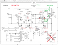
I updated today the diaphragm (attached now) cause the 1.0uf/400v coupling cap was changed weeks ago to 0.1uf/400v after recommended in last thread, about the opt yes are hooked into 5k tap from Tango FW-20S (no James trans).Also the 220 ohms from B+ was installed yesterday due the original 150 ohms reached 340V B+ yesterday when wall voltage rise to 126V from wall.
About the old Cunningham 345 Globe tubes, I decided not used in this circuit due the risk. I prefer try keep the 45's to max 300V, now is sounding powerful even low frequencies.
Kmaier, about the NFB , is just curiosity how compare with and without it, I found having to much gain for my room right now , I didn't found speakers impedance curve - only found 8 ohms @ 400hz.
Attachments
2A3Summer & Kmaier,
I need revise all your recommendations and numbers VERY SLOWOOLY ! in the way that I can get the idea on what me to do with that on my amp. 2A3Summer already know that took me days to digest the recommendations from last thread (I'm slow & low technically).
Thanks.
after tried a weak 45 tube that still had, it match better, so returned the 150 ohms B+ resistors, now having 52.6v and 52.1v on bias voltages.
- Status
- This old topic is closed. If you want to reopen this topic, contact a moderator using the "Report Post" button.
- Home
- Amplifiers
- Tubes / Valves
- Single ended 45 constant current and bias voltage adjustments-help please