...Please make it lots of smaller holes! The inlaid alu sheet could work loose or worse. Plus it will affect the structrual integrity of the chassis...
Goodbye BIG HOLE! Hello, LOTS OF SMALLER HOLES!
Also, I'm still working through the best way to get the signal to the VU meters and to power the FESTOON lamp.
Any advice on this would be appreciated.
Kofi
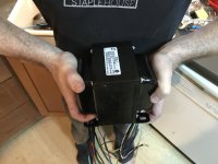
HOLY MOTHER OF GOD THE SHOWED UP AND IT IS STUPID BIG AND I CANNOT POSSIBLY USE IT IN THE AMPLIFIER HOLY HOLY HOLY COW IT IS TWENTY POUNDS AND ABSOLUTELY ENORMOUS.
I think I gotta find another transformer. I mean this is stupid big. I knew that 600VCT with 690mA would be big but you just can't imagine how big this thing is (see photos).
I have not been able to find a transformer that will give me with 300V / 380mA in a single transformer, but I really can't go with this one.
HELP!?!
KO--AAAGGH MY BACK!! --FI
So, here's what I've been able to dig up:
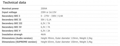
First, I could go with a toroidal transformer from Toroidy (see attached specs). This would be lightweight and would solve all of my issues with B+ and heater current, but I'm not sure I have complete confidence in that decision based on some earlier feedback.
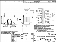
Another option would be to go with the ClassicTone #40-18042 (again, see attached specs). This would address the size and current issues and would weight about half what the Hammond clocks in at, however I would have to have a separate transformer to power the heaters as they will demand around 7A total.
I also shot a request to Edcor to see about a custom job, but I'm guessing this will take too much time and cost too much money.
Whaddaya think?
Kofi
Attachments

Looks good! And I'm assuming I can parallel the secondaries to double the current throughput, correct?
What is the downside of the toroidal? Why don't more builders use it? I know that toroidal OPTs are very sensitive to current imbalance (core saturation), but what about the power transformers?
Kofi
What is the downside of the toroidal? Why don't more builders use it? I know that toroidal OPTs are very sensitive to current imbalance (core saturation), but what about the power transformers?
Kofi
You showed a 600VCT xfmr. I was talking about using it that way, and assumed you needed the center tap, but if you used a FWB then, yes you could parallel the secondaries. The spec sheet does say that 20% more current is available at 60Hz. I used their toroids on several builds with no issues, but they do get a little warm running close to rated power. Oh, and they have nice steel covers to go with them.
Sounds good.
So I'm looking at the 400VA / 320V job (more beefier for cooler running, I'm hoping). I think you were thinking I could create a center tap by connecting the yellow and white leads together and using that as the CT and using the single yellow and single white as the ends of the secondary? That would double the current throughput?
Been a while since I dealt with Toroids-- back my my Gainclone / Chip Amp days.
Yikes.
Kofi
If you were to put the AS-4T320 windings in series to provide a center tap, then no, that will not double the available current, it will give you 640VAC center tapped, at 0.63A. Paralleling the secondaries will double the available current, but then you will need a full-wave bridge since you will have no center tap. But if you only need 380mA, the center tap scenario seems like it will still give you a good margin.
")
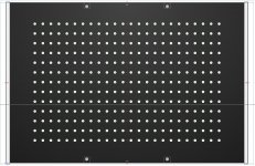
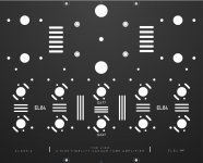
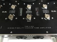
More to come soon, but wanted to share what I believe to be the final design of the top plate of the amplifier.
I was unable to justify using the M O N S T E R power transformer from Hammond and no other EI I could find ready-made would do the job right, so I went with the Antek AS-2T300 - 200VA 300V toroidal as it meets both the power and heater current requirements.
I became concerned about the ventilation of the toroid as I ordered the accompanying steel cover. Initially, I had added some ventilation holes underneath the toroid, however I thought that it might be venting *inside* the warm chassis and would wind up getting warmer or maintaining its heat rather than cooling.
My current plan is to raise up the transformer and cover off the top plate a few mm and have it vent into the cooler air above.
Comments? Questions? Ire?
KOFI
Holy cow! A lot has happened!
Here's a status:
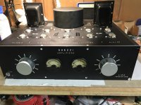
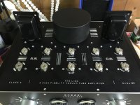
All parts have been received and I'm now only waiting on the Edcor OPTs. I finally pushed the button on the chassis and it looks incredible (take a gander!).
While the toroidal transformer would not have been my first pick, I think it looks really nice on the chassis.
I'm currently wiring the heaters and remembering how much I HAAAAAAAATE wiring heaters. That's always the worst part to me, but so far so good.
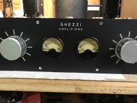
The Sifam meters really do look neat-o and will be illuminated by a 12V LED and bounce around to the music and stuff. I wound up getting an op amp buffer circuit PCB from JLM audio which I'm hoping will prevent distortive feedback to the signal when running the meters.
Lots of wiring to come soon!
Kofi
I was unable to justify using the M O N S T E R power transformer from Hammond and no other EI I could find ready-made would do the job right, so I went with the Antek AS-2T300 - 200VA 300V toroidal as it meets both the power and heater current requirements.
I became concerned about the ventilation of the toroid as I ordered the accompanying steel cover. Initially, I had added some ventilation holes underneath the toroid, however I thought that it might be venting *inside* the warm chassis and would wind up getting warmer or maintaining its heat rather than cooling.
My current plan is to raise up the transformer and cover off the top plate a few mm and have it vent into the cooler air above.
Comments? Questions? Ire?
KOFI
Holy cow! A lot has happened!
Here's a status:
All parts have been received and I'm now only waiting on the Edcor OPTs. I finally pushed the button on the chassis and it looks incredible (take a gander!).
While the toroidal transformer would not have been my first pick, I think it looks really nice on the chassis.
I'm currently wiring the heaters and remembering how much I HAAAAAAAATE wiring heaters. That's always the worst part to me, but so far so good.
The Sifam meters really do look neat-o and will be illuminated by a 12V LED and bounce around to the music and stuff. I wound up getting an op amp buffer circuit PCB from JLM audio which I'm hoping will prevent distortive feedback to the signal when running the meters.
Lots of wiring to come soon!
Kofi
Attachments
Quick question on the Anteck toroid. There are dual secondaries for the heater supply, which I had originally intended to parallel, however each secondary is wired with the same color (BRN - BRN for one secondary and BLU - CLU for the other).
Is there a way I can determine the phase for each same-colored wire so I can parallel these?
Kofi
Kofi
Is there a way I can determine the phase for each same-colored wire so I can parallel these?
Kofi
Kofi
I would double check the datasheet (it seems that for some of the larger ones there are no data sheets) because that's not usually how it is done with Antek transformers.
I've used a lot of them and usually you parallel the same colored wires from the matching secondaries to place in parallel.
I've used a lot of them and usually you parallel the same colored wires from the matching secondaries to place in parallel.
I've also used a lot of the Anteks, and yes the wire colors often differ than what is shown on the drawings. I can't absolutely guarantee this to be true in every case, but I've found that the winding wires exit the xfmr body in order of the windings. So in order, the first and third heater wires would pair with the second and forth wires if your going to parallel them. That would be a good starting point to try as nerdorama said.
Last edited:
Thanks, all. Much appreciated.
If all goes will I will be firing it up today and will address the heater AC as you described.
On another note, I was reading up on star grounding last night and I'm challenging my own method based on what I read.
Normally, I make 'local' star grounds for each stage (preamp / power) and attach them to the chassis at the BACK of the amplifier along with the PSU ground (one connection to chassis). Then I attach the earth connection to the chassis right next to the AC inlet (second chassis connection).
Based on what I have been reading, it may be better to attach both signal and power - near the SIGNAL input rather than at the PSU negative. I have seen that some people float the signal return rather than connect it to the PSU negative and chassis but that seems scary to me.
Any guidance?
Kofi
I wire amp grounds similar to what you have described.
All inputs are isolated from the chassis. The input signal grounds only connect to the input jacks (not the chassis) and run back to the preamp section signal ground, including the volume control signal ground. That ground goes to the main star ground, with the star ground isolated from the chassis. Same for the power section, back to the main star ground. The speaker output ground also goes to the star ground point. It is important to run the main rectifier ground directly to the first filter capacitor, and then to the star ground point.
I had a problem once with a laptop power supply injecting noise onto the signal ground, so I have been using a ground breaker for connection from the signal ground to chassis ground at the power entry chassis ground point. No more noise. I use what is described here in point #9: Earthing (Grounding) Your Hi-Fi - Tricks and Techniques
Last edited:
- Status
- This old topic is closed. If you want to reopen this topic, contact a moderator using the "Report Post" button.
- Home
- Amplifiers
- Tubes / Valves
- Kofi Annan in: "Tube Amp for Multi-Way Speakers"