True, its more sensitive to apply extra, but when feasible its welcome.
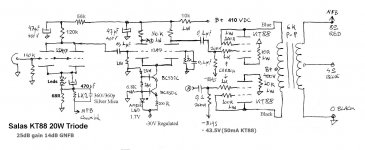
This 20W amp took 14dB GNFB easily for example. I had it at 9dB initially but when I added +5dB extra feedback is sounded better. Did not get harsher, only cleaner. Note that I was using the 8 Ohm tap on 4 Ohm load so the reflected impedance was changed on the primary.
This 20W amp took 14dB GNFB easily for example. I had it at 9dB initially but when I added +5dB extra feedback is sounded better. Did not get harsher, only cleaner. Note that I was using the 8 Ohm tap on 4 Ohm load so the reflected impedance was changed on the primary.
Attachments
Because of current hogging, forget PPP EL84/6BQ5s in a self biased amp.
Different O/P "iron" for EL34s than 6L6 family tubes. Edcor's CXPP60-4K should be OK, but make certain to roll infrasonic noise off at the amp's I/P. A single RC high pass pole whose F3 is in the 16 to 18 Hz. range gets the job done.
There's little to be gained by reinventing the wheel. Use Mullard's original 5-20 as the starting point, for a self biased PP EL34 O/P stage.
BTW, Mullard was trying to sell tubes that they manufactured, when the 5-20 design was published. The topology is fine, but the high RP/low gm 12AX7/ECC83 is a poor choice for the LTP.
i got very good results with a 6dj8 input tube and 6sl7 ltp stage in a JJ6L6GC pp amp i made a couple of years ago...
Attachments
Generally the figure of merit for global NFB is considered to be around 20dB - somewhat arbitrary, but that is enough for a 10 fold reduction in both source impedance and distortion, it also means the multiplicative products are low enough that you no longer care too much about them.
Probably nothing but a rule of thumb on the old hifi highway here in Boston.
Transformers are an excellent way to get galvanic isolation (ground loops, etc) and super high CMRR for induced hum pick up. So if you need balanced this is what I would do. (Kevin Carter at K&K Audio is who I would recommend you talk to about Lundahl's input transformers if you go this route. Yeah shameless plug, he's a friend. )
)
I use no global NFB these days so take that as purely anecdotal. I do however use a lot of transformers...
Probably nothing but a rule of thumb on the old hifi highway here in Boston.
Transformers are an excellent way to get galvanic isolation (ground loops, etc) and super high CMRR for induced hum pick up. So if you need balanced this is what I would do. (Kevin Carter at K&K Audio is who I would recommend you talk to about Lundahl's input transformers if you go this route. Yeah shameless plug, he's a friend.
)I use no global NFB these days so take that as purely anecdotal. I do however use a lot of transformers...
i got very good results with a 6dj8 input tube and 6sl7 ltp stage in a JJ6L6GC pp amp i made a couple of years ago...
Just wondering about the alignment of the transformers? Can you get away with the power transformer having the same alignment as the OPTs? Is that the advantage of the bell ends?
WOW! Guess I shouldn't have gone to bed early!
Rongon-- BIG thanks to you for modeling it stem to stern. I know that must have taken a while! Thank you so much!
That is EXACTLY what was happening with my LTSpice model. I swapped the phase of the splitter and was able to twiddle away with NFB after that.
Not sure why, but I was able to get about 45W out before clipping on my model with 400mV in? I have to Boot Camp over to the Windows side (from the Mac / iOS side) to make the simulation work, so I'll post mine in a bit along with relevant THD.
Any concerns about the need to balance the current between each PPP pair? I believe the earlier advice was that it may not make much difference as long as I am able to get matched quads / octets or that a trimpot may be added to assist with balance.
Kofi
Rongon-- BIG thanks to you for modeling it stem to stern. I know that must have taken a while! Thank you so much!
Also, if the polarity of the feedback signal is in phase with the input signal, the two will be additive (positive feedback) and LTspice will go nuts.
That is EXACTLY what was happening with my LTSpice model. I swapped the phase of the splitter and was able to twiddle away with NFB after that.
Not sure why, but I was able to get about 45W out before clipping on my model with 400mV in? I have to Boot Camp over to the Windows side (from the Mac / iOS side) to make the simulation work, so I'll post mine in a bit along with relevant THD.
Any concerns about the need to balance the current between each PPP pair? I believe the earlier advice was that it may not make much difference as long as I am able to get matched quads / octets or that a trimpot may be added to assist with balance.
Kofi
WOW! Guess I shouldn't have gone to bed early!
Rongon-- BIG thanks to you for modeling it stem to stern. I know that must have taken a while! Thank you so much!
No worries! I was curious to see what would happen, so it was fun. I'm seriously thinking of building a triode-wired version of this, to get maybe 8 to 10 W per channel. That would be enough for my needs. I have the iron and a chassis hanging around, so I should do it. But I have other unfinished projects in the way...
That is EXACTLY what was happening with my LTSpice model. I swapped the phase of the splitter and was able to twiddle away with NFB after that.
Not sure why, but I was able to get about 45W out before clipping on my model with 400mV in? I have to Boot Camp over to the Windows side (from the Mac / iOS side) to make the simulation work, so I'll post mine in a bit along with relevant THD.
Your results will depend on the models you use for tubes and transformer. My OPT model is of a hypothetical OPT from a Dynaco Stereo 70, with measured coil resistances added from the real thing. They differed a bit from the model I downloaded, so my results may or may not more closely reflect reality than others'. I do know that a real-life Stereo 70 is capable of delivering about 20W max per channel, so when the sim gives 20Wpc I figure it's doin' it close to right. YMMV of course.
Any concerns about the need to balance the current between each PPP pair? I believe the earlier advice was that it may not make much difference as long as I am able to get matched quads / octets or that a trimpot may be added to assist with balance.
Paralleling spreads out the differences of individual tubes' current draw, so it should be possible to mix 'n match positions of the 8 EL84s to get reasonably good balance. With an EI or C cored OPT you can have a few milliamps of imbalance without much penalty. With a toroid core OPT it's more likely that you will have to be more careful about keeping current balanced between the primary windings. Beyond that things get complicated, and I'm not knowledgeable enough to go beyond that level of understanding. Maybe someone else would be willing to dive in here and clarify?
--
Hey! Sorry for the couple-day hiatus, but I got distracted with non-amplifier events.
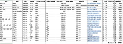
I am still working through the BOM for the power supply and such, but wanted to share my working copy now (attached as Excel file and picture). Please feel free to review and mock my choices as you see fit.
Kofi
I am still working through the BOM for the power supply and such, but wanted to share my working copy now (attached as Excel file and picture). Please feel free to review and mock my choices as you see fit.
Kofi
Attachments
I noticed your (Kofi) concern about product liability, so I will make a few un-requested comments, and hope that I don't offend anyone with the free advice. I practiced as a trial lawyer for fourteen years, and retired from the practice in 1996, burnt out.
Basic: YOU are responsible for what YOU do, incorporated or not. A couple of attorneys I knew had to be bailed out because they confused "liability for personal actions" with "liability for company actions", and really screwed up their clients' lives. Screw-ups of the first order. The whole point of hands-off stock ownership (and that literally means HANDS OFF, so no involvement in management) is that hands-off shareholders are only liable for corporate actions up to the value of their shares. If things go south, they can throw their hands up, say So Sad, Too Bad and walk away, free of further obligations.
If you are in the middle of it, like being the CEO, or the builder or designer, then you do not get that protection. Insurance is kind-of nice when your damages are covered. What makes insurance indispensable is the blood-sucking pit-bull defense attorneys the insurance companies have on staff who will fight to the last drop of the plaintiff's blood to keep from paying a penny, and better yet, the insurance company pays those defense lawyers, not you. Coverage for a one-off policy may be relatively inexpensive. The insurer may require you to get a Licensed Professional Engineer to bless your work. If you cannot afford to do this, or no insurer will cover you, that is a huge hint from the Universe that maybe you shouldn't do this (so take the hint). Build it in your own home for your own use, keep adequate homeowner's insurance up to date, and you are probably covered. Build it for use in a commercial environment, and liability exposure can run into the millions.
My first boss made almost a million off a bolixed-up farm harrow with a home-made hitch that crippled and maimed his client. His client got the other two-thirds of the settlement. Please don't be naive enough to think that actual innocence from negligence will get you out of it - it won't, and your homeowner's insurance won't touch it, not if you intended to build it for a commercial environment. This is not legal advice. This is just my own opinion, formed after hard, sad, experience. Listen to your attorney, but don't skip the product liability insurance. If you design and build it for commercial use, no form of incorporation can protect you, but insurance will.
AllIsParadox,
No offense taken whatsoever. Thank you so much for your reply.
I have taken your comments very seriously-- so much so that I was able to sign up for product liability insurance today, which I believe will cover me for the issues you represented here. I also have a couple of calls out to lawyers to review my situation and offer further advice and / or recommend possible changes to this policy as needed.
As you mentioned, it was actually quite inexpensive and will not only provide coverage but peace of mind at a very reasonable price.
Here's a follow-up question for you:
I'm assuming you mean that if any damages are incurred by the customer that related to my negligence, my product liability insurance will pay out up to the maximum policy amount. Is that correct?
Again, thank you so much for your response. You told me what I needed to hear and I appreciate it.
Kofi
No offense taken whatsoever. Thank you so much for your reply.
I have taken your comments very seriously-- so much so that I was able to sign up for product liability insurance today, which I believe will cover me for the issues you represented here. I also have a couple of calls out to lawyers to review my situation and offer further advice and / or recommend possible changes to this policy as needed.
As you mentioned, it was actually quite inexpensive and will not only provide coverage but peace of mind at a very reasonable price.
Here's a follow-up question for you:
Please don't be naive enough to think that actual innocence from negligence will get you out of it - it won't, and your homeowner's insurance won't touch it, not if you intended to build it for a commercial environment.
I'm assuming you mean that if any damages are incurred by the customer that related to my negligence, my product liability insurance will pay out up to the maximum policy amount. Is that correct?
Again, thank you so much for your response. You told me what I needed to hear and I appreciate it.
Kofi
Just wondering about the alignment of the transformers? Can you get away with the power transformer having the same alignment as the OPTs? Is that the advantage of the bell ends?
the OPT's were mounted vertically on its short side, the power traffo is mounted horizontally on its longer side, so the coil axis are 90 degrees...
Kofi: I am very glad to know that you have insurance.
There are people that believe that when they have done nothing wrong, they can go without insurance coverage (I call it "going naked"). I have seen objectively innocent people stuck with paying court judgments when they might have gotten out of it with a good trial lawyer. Not fair, but life is not fair. Going without some kind of insurance is foolish for product liability.
As an individual, your recoverable assets (what a plaintiff's attorney can squeeze out of you) are usually minimal compared to policy payouts. If damages are terribly severe, many, maybe even most, resolutions boil down to "pitch the policy". Plaintiffs won't get significant judgments out of you, so they don't try. They settle quickly for the maximum amount of the policy, even though it is far less than actual damages, and they leave you alone. You pay nothing more. That means you might avoid paying $5,000,000 in damages due to a policy with a $100,000 limit. No lawsuit ever gets filed, just a payment check cut and a general release signed.
As bargains go, it doesn't get much better than that. Again, not legal advice, and no guarantees from me, but I have seen this kind of result often.
Few non-lawyers are aware of the practice.
I am emphatically NOT recommending any specific policy amount. $100,000 might not be enough. $100,000 might be far too much. I certainly don't know. You puts down your money and you takes your chances.
I am sure other readers have had enough of this branch topic. If you have more questions, please direct them to your attorney or your insurance agent.
Thanks again for the advice. I feel much better now that I have insurance.
OK, so I'm moving forward and getting a parts list together, but it looks like I will need to ait eight weeks for Edcor to make OPTs. Hammond has an off-the-shelf job (the 1650RAP that's potted @5K primary / 100W. They also have the 1650N @4.3K / 60W.
Should I wait for the Edcors or press forward with the Hammonds to save some time? Is the quality of the Edcors worth the wait?
Kofi
Thanks for the reply.
I just called them and they are currently running 4 - 6 weeks on delivery. I will need to go with the Hammond power TX as it meets the needs of the amplifier very well, but I'll wait for the OPTs.
Working hard right now on parts orders and chassis layout. Will update again soon with all the stuff.
Oh-- and I need to add VU meters and was thinking about these. They don't need to be accurate-- just provide some pizzazz, so I'm hoping I can parallel them with the speaker outputs and throw a 3K6 in front of it to make that happen (i.e., would rather not have to make an op-amp buffer, if possible).
Any thoughts on that?
Kofi
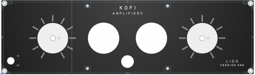
Hey!
It's taken some time, but I believe I have a viable layout. Sharing in case anyone has any comments or edits. More to come soon.
Kofi
I just called them and they are currently running 4 - 6 weeks on delivery. I will need to go with the Hammond power TX as it meets the needs of the amplifier very well, but I'll wait for the OPTs.
Working hard right now on parts orders and chassis layout. Will update again soon with all the stuff.
Oh-- and I need to add VU meters and was thinking about these. They don't need to be accurate-- just provide some pizzazz, so I'm hoping I can parallel them with the speaker outputs and throw a 3K6 in front of it to make that happen (i.e., would rather not have to make an op-amp buffer, if possible).
Any thoughts on that?
Kofi
Hey!
It's taken some time, but I believe I have a viable layout. Sharing in case anyone has any comments or edits. More to come soon.
Kofi
Attachments
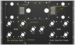
...I'd probably turn the 12AX7 and 12AT7 90° so that the phase splitter connections to each bank of output tubes are equidistant, this should help to make the HF behavior consistent on both channels.
I had them placed that way originally, but I had to make room at the dead front for the VU meters, which required me to move the small guys back. Let me see what I can do to remedy that...
I like the marketing pizzazz!
Gotta get the branding out there.
Kofi
Have you already bought and paid for the tubes? You could switch the 12AX7-12AT7 combination to a single 12DW7 per channel (pins 1,2,3 = 12AU7, pins 6,7,8 = 12AX7). JJ Electronics makes one that sells for $13 each. That's not crazy. You could orient each one so that its 12AU7-equivalent pins face towards the output tubes. JJ Electronic - ECC832 - 12DW7 You might have to change the biasing of the 12AU7-equivalent half (the cathodyne), but since that part runs with 100% NFB, swapping tube types for that shouldn't change performance much. What's funny is that you would end up with the same tube complement as the good ol' Dynaco ST35 (12DW7 --> pp 6BQ5). Maybe not a good idea. I don't know. It would simplify layout, though. Or... Would you have room for two 7-pin triodes and one 9-pin twin-triode? A single 6AV6 for each channel and a 12AT7 shared between both channels? https://frank.pocnet.net/sheets/093/6/6AV6.pdfI had them placed that way originally, but I had to make room at the dead front for the VU meters, which required me to move the small guys back. Let me see what I can do to remedy that...
I hope when this project is completed you post a final schematic.
I have watched from the side lines and it is exciting watching you guys contribute and help.
Back to my seat in the stands......
Final schematic incoming, johnnyk9! Thanks for subscribing! You may yet regret it!
Have you already bought and paid for the tubes?
You could switch the 12AX7-12AT7 combination to a single 12DW7 per channel (pins 1,2,3 = 12AU7, pins 6,7,8 = 12AX7). JJ Electronics makes one that sells for $13 each. That's not crazy. You could orient each one so that its 12AU7-equivalent pins face towards the output tubes.
[url=https://www.jj-electronic.com/en/ecc832-12dw7]JJ Electronic - ECC832 - 12DW7
...
Maybe not a good idea. I don't know. It would simplify layout, though.
It IS a good idea, however I just changed the layout to accommodate the preamp tubes in their original places.
Or...
Would you have room for two 7-pin triodes and one 9-pin twin-triode?
A single 6AV6 for each channel and a 12AT7 shared between both channels?
https://frank.pocnet.net/sheets/093/6/6AV6.pdf
Same answer, I'm afraid. Been movin' stuff around all day and Kofi ain't-a-gonna moverin' it back!
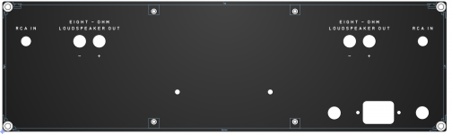
Anyway, wanted to share what I believe is the final layout of the panels. I got concerned about ventilation after reading Morgan Jones' aptly named (and wonderful) Building Valve Amplifiers. [SPOILER: It's about uilding-bay alve-vay plifiers-bay]. In it, he opines on how builders leave vent holes on top but close off the bottom of the amp when they should use perforated sheet metal to ensure air flow will move through the chassis. Well, I did ya one better MJ, cuz I made the bottom plate have a BIG HOLE. Nothing beats a BIG HOLE, amirite?
Of course, I'll safe-t-fy it with some inlaid hole-y sheet aluminum, but right now it's fun to see the BIG HOLE!
Take a look and let me know what you think. The two teeny holes in the back panel are for the choke-- could not fit it anywhere else and you know what Kofi just said about moverin' stuff, right?
Also-- need some help with the VU meters whenever someone can stomach it. I wound up going with these babies and I believe they have a 6-volt FESTOON lamp as illumination. I'm assuming these can run from AC and that I can power them from the heaters, but wanted to confirm. Also, hoping I can run these straight off the speaker outputs with little voltage dividering and can avoid making a two-channel buffer amp to serve up the signal to the meters.
Anyone? ANYONE?
Kofi?
Attachments
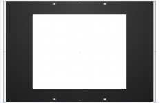
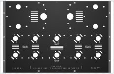
Hole in The bottom is BAD idea. Any opening large enough to put your hand through is a horrible idea. Someones 5 year old will find it. Or some idiot will try to pick it up and grab a hot capacitor. Please make it lots of smaller holes! The inlaid alu sheet could work loose or worse. Plus it will affect the structrual integrity of the chassis...
- Status
- This old topic is closed. If you want to reopen this topic, contact a moderator using the "Report Post" button.
- Home
- Amplifiers
- Tubes / Valves
- Kofi Annan in: "Tube Amp for Multi-Way Speakers"