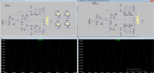
I have a model for a Dynaco A470 that I like to use as my 'generic' ~5k:VC OPT model. I put your proposed circuit into LTspice and let it do its thing. This looks like a nice circuit! At least in simulation...
My understanding of toroids vs. EI cores is that toroids can't take much current imbalance before core saturation results in odd order harmonics in the output. The Baby Huey design uses a constant current sink in each EL84 cathode to combat this.
On the other hand, if the current draw is averaged across two EL84s per side, it should be possible to pick a set that runs with pretty good current draw balance.
Perhaps use a pot to balance current draw between pairs of EL84s. A combination of in-the-ballpark matching of tubes and a balance pot might do the trick. ??
Sounds about right to me. Was hoping I wouldn't need to make eight bias blocks. Also, I'm assuming the pots would need to be twiddled once in a while to account for component drift over time.
Or, maybe we just go with these guys from Edcor, unless you can recommend other OPTs that don't cost a mortgage payment?
YES!
Kofi
Or, maybe we just go with these guys from Edcor, unless you can recommend other OPTs that don't cost a mortgage payment?
I put your proposed circuit into LTspice and let it do its thing. This looks like a nice circuit! At least in simulation...
YES!
Kofi
Rongon makes a good point about the toroid, they are not tolerant of much DC on the primary, but you need to look at the specification, if it is at least 5% of rated primary current you can probably get things close enough with garter bias.
I would not go dual mono unless you really want to amp the thing up quite a bit.
You can safely parallel the secondaries and use a single bridge rectifier, a pair of 100uF/450V caps and a 1 - 2H choke with a DCR of 50 - 100 ohms (The lower the better) in a classic pi-filter.
An Edcor output transformer with 3 - 4K primary Z ought to a be good option. A pair of Dynakit ST-70 output transformers is not too far off the mark either and while not optimum would provide pretty decent performance.
Rongon makes a good point about the toroid, they are not tolerant of much DC on the primary, but you need to look at the specification, if it is at least 5% of rated primary current you can probably get things close enough with garter bias.
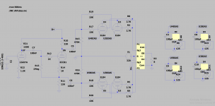
Started noodling on a simple bias block using the LM7805 (see attached). Maybe this is a simple solution that would allow current regulation and keep the balance between the pairs?
I would not go dual mono unless you really want to amp the thing up quite a bit.
You can safely parallel the secondaries and use a single bridge rectifier, a pair of 100uF/450V caps and a 1 - 2H choke with a DCR of 50 - 100 ohms (The lower the better) in a classic pi-filter.
Ah! Yes! The old 'parallel the secondaries' trick, eh? Great idea.
An Edcor output transformer with 3 - 4K primary Z ought to a be good option. A pair of Dynakit ST-70 output transformers is not too far off the mark either and while not optimum would provide pretty decent performance.
I think it would be neat to have the power supply and the OPTs all toroidal, but the practical move may be to just go with the Edcors.
Thoughts on bias blocks + toroidal vs. old school + EI / Edcor?
Kofi
but you need to look at the specification, if it is at least 5% of rated primary current you can probably get things close enough with garter bias.
Blew right past this initially. No experience with garter / Blumlein. And not sure I understand the '5% of rated primary' issue. What would need to be >=5%?
Kofi
Attachments
Current balance between sides of the winding would need to be better than the maximum imbalance % the transformer can tolerate.
I would go with exactly zero toroids even for the power supply - this an amp that needs to be simple and rugged - so I would go old school pretty much all of the way.
I assume the person you are building this for is paying for it. I'd go with all Edcor iron, likely there is a power transformer that fits the task, otherwise have a look at Hammond, lately their quality seems to have improved.
TBH I don't build tremendously simple amps these days, but I've figured out what I need to do to make them reliable as you will too.
Remember the context where this amplifier will be used - it's unlikely anyone will even notice whether the amp in question has the top octave or not..") It just needs to play for an extended period of time without eating the modern tubes used in it. Talking of which 6P14P-EV or ER (~7189 equivalent) will give very long service. Buy NOS military surplus from Russian or Ukrainian dealers on eBay.
It just needs to play for an extended period of time without eating the modern tubes used in it. Talking of which 6P14P-EV or ER (~7189 equivalent) will give very long service. Buy NOS military surplus from Russian or Ukrainian dealers on eBay.
I would go with exactly zero toroids even for the power supply - this an amp that needs to be simple and rugged - so I would go old school pretty much all of the way.
I assume the person you are building this for is paying for it. I'd go with all Edcor iron, likely there is a power transformer that fits the task, otherwise have a look at Hammond, lately their quality seems to have improved.
TBH I don't build tremendously simple amps these days, but I've figured out what I need to do to make them reliable as you will too.
Remember the context where this amplifier will be used - it's unlikely anyone will even notice whether the amp in question has the top octave or not..
It just needs to play for an extended period of time without eating the modern tubes used in it. Talking of which 6P14P-EV or ER (~7189 equivalent) will give very long service. Buy NOS military surplus from Russian or Ukrainian dealers on eBay.I have 94dB DIY speakers that dip into four Ohm. I had a 20W tube amp. Was loud with nice sound but with a 50W Mosfet amp surely they rocked better in peaks. And when I really press them a 200W @ four Ohm amp rocks them best. Having spare power always shows but don't design for below 50W on a 93dB sens speaker is my experience. I mean some weaker amp it could be nice until you knew nicest.
This amplifier will play background music in a restaurant through who knows what speaker.. LOL
The amp discussed will do at least 30W from experience and should be good for about north of 107dB with the speakers in your example.
I observed the same thing when I went from 8W of SE power to 20W of SE power in my system FWIW, some it was better driver control, lower distortion, and the extra headroom.
TBH it doesn't have to be the ultimate expression of amplifier design, but it has to sound nice, be inexpensive, rugged and play continuously for long periods of time without any attention.
50W+ for 93dB speakers would be needed for really good dynamics and grip I am afraid
Don't know what grip is but I'll try to squeeze as much out os the amp as possible. It models at around 45W peak with no clipping with around 2.1% THD open loop, so maybe just some modest feedback?
Kofi
This amplifier will play background music in a restaurant through who knows what speaker.. LOL
What? I thought it was for an enthusiast. No restaurants or coffee shops are mentioned in post#1. Just that the amp it will be made by Kofi.
Don't know what grip is but I'll try to squeeze as much out os the amp as possible. It models at around 45W peak with no clipping with around 2.1% THD open loop, so maybe just some modest feedback?
Kofi
Yes some modest NFB would do
P.S. Welcome back man long time no see
What? I thought it was for an enthusiast. No restaurants or coffee shops are mentioned in post#1. Just that the amp it will be made by Kofi.
Well, it will be in a kinda hipster bar and he does want to play electronic music through it for events. I wouldn't mind going bigger if I need to, but it unclear ro me if he would see the value in the additional power.
He *is* used to pro audio, however, which I believe has about one zillion watts available. Additional power may be worth considering. I'll sleep on it.
P.S. Welcome back man long time no see
Great to hear from you, Salas. And great to be back.
Kofi
Hmmm... Pro audio, as in live on stage electrified music audio? That's LOUD these days.
I don't know if this will be unnecessarily complex, but dividing the frequencies up and feeding about 200Hz and up to a stereo tube amp and the lower frequencies to a reasonable solid state amp of 100Wpc or so would be a good way to get that 'tube sound' (and look) in the mix, while having power reserves for parties, etc.
I used to have a push-pull 2A3 amp (6Wpc) feeding the mids and tweeters of a pair of Snell Type C speakers (about 90dB/W 4 ohms), with a Hafler 50Wpc power amp powering just the woofers in the Snells. The Snells are bi-wired, so it was easy enough to wire it up using the speakers' built in passive crossovers. The Hafler amp has level controls on its front panel, so I could balance the level of the woofers with that of the mids/tweets. It worked pretty well. Way loud enough for my medium-sized living room, and I think it sounded really nice.
One attractive part of doing it that way is that there are gazillions of decent solid state amps available for not a lot of money. You could even go Class D. But only if the speakers are bi-wired and will allow this kind of setup.
Just an idea. Please disregard if not appropriate for the situation.
--
PS - Just realized that this type of setup will only work if there is a 'master volume' control before the amplifiers, either from a 'passive preamp' or an actual line level preamp. That complicates things even more...
--
Last edited:
Rongon,
Thanks for the reply!
I have actually discussed such an option with the client, but I think I would consider this a 'Phase II' option after the initial amplifier is built.
As Kofi's mind is currently running south of 99.999% reliable, I would like to call in some 'relief minds' to answer the following questions:
1. I'm guessing I will need to apply some global NFB and assuming that I will need to run it from the 8R secondary tap back to the 12AX7A cathode between the bias resistor and, say a 100R to ground. Does that seem correct? Any alternatives?
2. Client wants 'cool meters', so I'm inclined to add some milliammeters to the front panel (these could be voltage meters as well, I suppose). Normally, I would take the current measurement from the power tube cathodes, but since there will be four of these per side, I'm not sure of the best approach. Any thoughts from your collective 'relief minds' would be appreciated.
3. He will be using it with the MasterSounds Radius 4V preamplifier. Can see any issues with this, but wanted to share to see if I should alter the voltage gain to accommodate.
4. He would like it to be able to function both with and without a preamp, so I'm thinking I should include stereo passive preamps (volume pots) along with a switch to defeat them if using a preamp. Eh? Eeeehhhh???
5. I am thinking through a sales agreement (you give me $X money down then the rest on delivery (like a mob hit)) and a manual that includes definitions of proper use (turn on, play music, turn off) and improper use (bring to beach and get loose with some Coors Light, take to romantic dinner and consummate sale after evening cocktails, lightly fry with onions and jicama, let cool and serve with guacamole). Any boilerplate stuff you guys have on hand?
Thanks for everything folks. All of you have earned an 'I Helped Kofi' T-shirt!
Kofi!
Talkin' preamps an' mixers
I see three pairs of outputs on the back of that mixer.
MASTER OUT - XLR; I assume they're balanced.
BOOTH OUT - Does that send a master mix to these outputs, or is this just a Send from the CH FOUR input pair?
AUX OUT - Similar question to that for Booth Out. Does that send a master mix to these outputs, or is this just a Send from the CH THREE input pair?
If the customer plans to connect the Master Out XLR outs to the amp, then you might want balanced inputs. Long-tailed pair instead of cathodyne? If the customer plans to connect either the Booth Out or Aux Out to the amp, then all stays as it was.
If the customer wants to use the Master Out XLR pair to connect to the amp, then you have to figure out how you want to handle the balanced input signal. Or do you want to unbalance it right at the amp's inputs?
You could put a pair of 1:1 input transformers on the amp's inputs. That way you could equip the amp with both balanced (XLR) and unbalanced (RCA) inputs, and use the transformer's secondary unbalanced (signal and ground), and that would go straight to the volume control(s) (either a stereo ganged pot or an individual pot for each channel).
I don't think you'd need a defeat switch for volume pots. Turning the pots all the way up is basically the same thing. A pair of 50k log taper pots could work as individual Left Channel and Right Channel "level" controls.
I'm sure someone else will have a better idea, but those are the first things that occurred to me...
--
3. He will be using it with the MasterSounds Radius 4V preamplifier. Can see any issues with this, but wanted to share to see if I should alter the voltage gain to accommodate.
I see three pairs of outputs on the back of that mixer.
MASTER OUT - XLR; I assume they're balanced.
BOOTH OUT - Does that send a master mix to these outputs, or is this just a Send from the CH FOUR input pair?
AUX OUT - Similar question to that for Booth Out. Does that send a master mix to these outputs, or is this just a Send from the CH THREE input pair?
If the customer plans to connect the Master Out XLR outs to the amp, then you might want balanced inputs. Long-tailed pair instead of cathodyne? If the customer plans to connect either the Booth Out or Aux Out to the amp, then all stays as it was.
4. He would like it to be able to function both with and without a preamp, so I'm thinking I should include stereo passive preamps (volume pots) along with a switch to defeat them if using a preamp. Eh? Eeeehhhh???
If the customer wants to use the Master Out XLR pair to connect to the amp, then you have to figure out how you want to handle the balanced input signal. Or do you want to unbalance it right at the amp's inputs?
You could put a pair of 1:1 input transformers on the amp's inputs. That way you could equip the amp with both balanced (XLR) and unbalanced (RCA) inputs, and use the transformer's secondary unbalanced (signal and ground), and that would go straight to the volume control(s) (either a stereo ganged pot or an individual pot for each channel).
I don't think you'd need a defeat switch for volume pots. Turning the pots all the way up is basically the same thing. A pair of 50k log taper pots could work as individual Left Channel and Right Channel "level" controls.
I'm sure someone else will have a better idea, but those are the first things that occurred to me...
--
If the customer plans to connect the Master Out XLR outs to the amp, then you might want balanced inputs. Long-tailed pair instead of cathodyne?
If the customer plans to connect either the Booth Out or Aux Out to the amp, then all stays as it was.
Great point! I'm checking with the client now, but hoping we won't need to make any design changes.
I'm having some trouble implementing gNFB in LT Spice for this design. I'll post my total failures in a bit, but can anyone offer advice?
Kofi
GNFB amount and square wave ringing damping will be very much a bench exercise. The output transformer and the whole layout will have it's practical behavior. You will judge THD benefits vs how many dB of NFB vs subjective tone vs how much square wave damping by the hundreds pF range capacitor to ride the Rf resistor yada yada yada.
But do you have enough open loop gain to spare some in GNFB to start with?
But do you have enough open loop gain to spare some in GNFB to start with?
Also, if the polarity of the feedback signal is in phase with the input signal, the two will be additive (positive feedback) and LTspice will go nuts.
Try swapping the polarity of the outputs from the cathodyne to the output tubes.
I don't know if this will hold up in real life, but the simulation I did predicts that with the amp running open loop, an input signal of about 200mV rms drives the amp to clipping at approx 18W rms output (THD = 1.46%).
9dB of NFB is predicted to change that to 800mV rms input to reach 20W rms out at 0.6% THD.
Is 9dB of NFB enough?
I've attached the .asc (LTspice) if anyone wants to double-check my work.
Try swapping the polarity of the outputs from the cathodyne to the output tubes.
But do you have enough open loop gain to spare some in GNFB to start with?
I don't know if this will hold up in real life, but the simulation I did predicts that with the amp running open loop, an input signal of about 200mV rms drives the amp to clipping at approx 18W rms output (THD = 1.46%).
9dB of NFB is predicted to change that to 800mV rms input to reach 20W rms out at 0.6% THD.
Is 9dB of NFB enough?
I've attached the .asc (LTspice) if anyone wants to double-check my work.
Attachments
It would be nicer if for 15dB of NFB, both for less THD and usefully less sensitivity for better SNR with modern system gain structures. But even 9dB brings a considerable improvement, yes.
P.S.
IMD (especially SMPTE) is a thing to watch for as much as THD or more. Tends to stick out in tube amps with small amounts of GNFB. That thing if left uncontrolled it fogs the sound in the presence of busier music signals. Say feed a 100Hz bass tone four times stronger than a 4kHz tone simultaneously and see how much it modulates it. If the 100Hz side bands are dancing higher than 0.1% around the 4kHz needle, then they start to become audible enough.
Yes, but with 15 or more dB of gNFB you'll have to be very careful about dynamic resonances, oscillation, etc. That takes lots of work, more than I've ever been able to accomplish.
I wonder if that's why these plate-grid ("Schade") feedback pentode designs have become popular around here. Without the OPT inside the feedback loop, I'd think it would be a lot easier to predict poles, zeros, and whatever else might oscillate or resonate.
--
I wonder if that's why these plate-grid ("Schade") feedback pentode designs have become popular around here. Without the OPT inside the feedback loop, I'd think it would be a lot easier to predict poles, zeros, and whatever else might oscillate or resonate.
--
- Status
- This old topic is closed. If you want to reopen this topic, contact a moderator using the "Report Post" button.
- Home
- Amplifiers
- Tubes / Valves
- Kofi Annan in: "Tube Amp for Multi-Way Speakers"