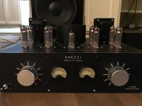
Rebuilt the power supply over the last two days to accommodate the chassis-mounted resistors. I was initially concerned about how much heat they were generating during testing until I actually mounted them to the chassis and saw that they were running pretty cool (Kofi's Hot Tip: remember to chassis mount chassis-mount resistors. If only I could come up with a mnemonic for this...)
With the 25R resistors installed the B+ is running about 335VDC which, per Kevin's post, is cool like The Fonz.
Ran it open loop on the main speakers today and despite a connection on the left channel pot crackling (two terminals are intermittently shorting-- easy to fix) and a bit of high-frequency hash (looks like a little bit of ringing on the supply), things seem pretty nice.
My quick-and-dirty calcs show just under 20W before clipping (open loop) and it really shows in the soundstage. Despite the HF spray, it feels a whole lot more powerful than the Baby Huey and the bass punch is just stupid.
Next step is to get the VU meters bouncing. Unfortunately, I will need to make a 12VDC supply for both the LEDs and the op amp that will power the meters. I have a 12V transformer left over from a prior project that I'm planning to use, but I'm almost wondering if I should just hot glue a wall wart power supply into it and call it a day.
Thoughts?
Kofi
Attachments
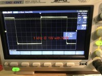
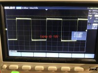
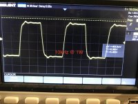
Some square wave testing today.
Looks like I've got some ringing. Maybe a zobel would help?
Put it on full blast in the house today. Seems like it has a ton of power-- very details and lotsa soundtange and bass. Maybe a little high-frequency warble, which is what the square wave met be telling me.
Would a zobel be appropriate here?
Kofi
Attachments
That's far from the worst square wave behavior I've seen,
- I'd start by removing C11 in the feedback network and retesting.
- A small cap and resistor (step network) from 12AX7A voltage amplifier plate to GND maybe using decade boxes to find the right compromise if you have them. (Lead dress is important if you do this.)
- What is your open loop gain from the tap you derive your feedback from? I'm thinking you may have very little feedback which is why it is comparatively well behaved.
- Once close test into 8 ohm in parallel with 1uF and make sure amplifier remains stable.
- A zobel network may help. (start with something like 33 ohm 1W in series with 0.1uF across 16 ohm to GND to test).
- If you have an FFT analyzer measuring phase and magnitude response of amplifier to baseline and then experiment with compensation component values to help you to compensate it.

That's far from the worst square wave behavior I've seen,
Or leave as is as long as it does not oscillate into the 8ohm//1uF cap load.
- I'd start by removing C11 in the feedback network and retesting.
- A small cap and resistor (step network) from 12AX7A voltage amplifier plate to GND maybe using decade boxes to find the right compromise if you have them. (Lead dress is important if you do this.)
- What is your open loop gain from the tap you derive your feedback from? I'm thinking you may have very little feedback which is why it is comparatively well behaved.
- Once close test into 8 ohm in parallel with 1uF and make sure amplifier remains stable.
- A zobel network may help. (start with something like 33 ohm 1W in series with 0.1uF across 16 ohm to GND to test).
- If you have an FFT analyzer measuring phase and magnitude response of amplifier to baseline and then experiment with compensation component values to help you to compensate it.
Wow! Thanks for the guidance!
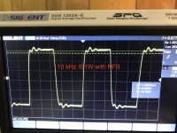
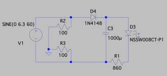
Here are some screenshots without the NFB. Not much difference. There's a noted reduction in gain with the NFB in, so it's doing its gain-reduction thang, just not improving the square wave.
Based on the response of the SWAT team that busted my door down last night due to my 'community disturbance', there's still PLENTY of gain left for NFB if I need to go bigger. I am currently taking the feedback signal off the 8-ohm tap (same as speaker output). Taking it from the unused 16R tap would increase the feedback, correct?
Also, I noted during my voltage tests that the AC on the heaters is at 6.53V. Should I drop a few volts or is this within running range?
Kofi
Attachments
Last edited:
Agh! So I need a 12VDC supply for the VU buffer circuit and the LEDs in the meters. I just don't have any room left for another transformer, so I'm thinking I can sun a voltage doubler off the filament supply and rectify it for the DC supply.
Any reason that would be a bad idea?
Kofi
Any reason that would be a bad idea?
Kofi
Some square wave testing today.
Looks like I've got some ringing. Maybe a zobel would help?
Put it on full blast in the house today. Seems like it has a ton of power-- very details and lotsa soundtange and bass. Maybe a little high-frequency warble, which is what the square wave met be telling me.
Would a zobel be appropriate here?
Kofi
That's actually a quite nice response for a 10kHz square wave. I wouldn't worry. The slight resonance - if I read your scope trace right - seems to be at around 50kHz and well damped, so if the amplifier is otherwise stable I wouldn't do anything.
You could measure the amp to other impedances, that might give a different response. Maybe a 47 ohm resistor instead of an 8 ohm dummy load. And try a 2,2µF cap in parallel with the 8 ohm dummy and see if the amplifier is still stable. Some overshoot with a cap in parallel with the resistive dummy load is to be expected, but the amplifier should still be stable. If this is true, don't worry.
I'll do a little more measuring tomorrow and post the results. It honestly sounds so good to me that I'm inclined to leave it alone.
The amp looks great!, and from your description it sounds great as well. Great job!
Thanks, Scott. Really appreciate all your help.
It's still nagging me that I have 6.53V on the heaters instead of 6.3. Should I be worried about it?
Kofi
It's still nagging me that I have 6.53V on the heaters instead of 6.3. Should I be worried about it?
Kofi
That's a non-issue. Well within tolerances. Stay under 6,7 volts and it's A-OK.
- Status
- This old topic is closed. If you want to reopen this topic, contact a moderator using the "Report Post" button.
- Home
- Amplifiers
- Tubes / Valves
- Kofi Annan in: "Tube Amp for Multi-Way Speakers"