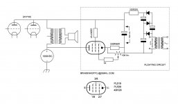
Having a 40w 6k6 push pull output transformer I wanted to use it as a single ended one for a PSE VT4C ( the output impedance seemed about right). I therefore needed a tube circuit that would cancel the output tubes anode currents to avoid magnitization of the airgapless core and one that would be both simple and cheap. The current drawn by the tube had to be equal to and opposed to the anode currents of the VT4C's. The schematic shows the VT4C's and the 1000v powersupply and the added floating PL519 circuit whose anode current runs in the opposite direction through the output transformer. Both are drawing 100ma and thereby cancel each other.
The 519 is used as a penthode which has a high output impedance even made higher because of the nondecoupled cathode resistor so as not to ac load the output tubes. With the 10k pot we can vary the anode current from 40- 150ma. With a dvm across the outputs primary we adjust the pot until we see zero volts (within a few tens of a volt).
As the indirectly heated 519 takes some time to settle we must readjust the pot after a few minutes. As the floating counter current circuit carries a 1000v I built it on a piece of wood and a cage around it to prevent an accidental touch. The pot has a plastic knob for the same reason. The 40v, 1A transformer feeds the filament and by tripling the dc output also the anode and screen voltages of the 519. Four 220 mu\ 200v electrolytics take care of the smoothing. ESRC tubes sells the 40KG6A (=PL519) for $12 so the total cost will be about $35 for one channel.
I'm quite happy with the outcome and feel no need to buy a big and costly OT. I know many audio amateurs do have an unused PP OT lying around so I suggest they try the above for a change. The anode current of the 519 can be adjusted over a wide range so it can be used with all kinds of tubes (845, GM 70, 811-3, 811-10, KT88 etc.). You don't have to worry about dc overloading a (possibly) small OT as there is no dc. To prevent ac overloading don't use the amp at full power. Any other tube can be used instead of the 519 but sweep tubes are cheap and strong and will last a life time in this application.
Attachments
A quite interesting current bucking arrangement. Most do it with one half the primary which sacrifices transformer coupling to a degree. But aren't the primary windings anti phased so coupling is compromised as well? Anyway I seem to remember something about this full primary bucking system years ago in the famous Japanese "MJ Stereo Technology" (Mu Sen To Zi Ken). I had planned to experiment with it but just never got around to it. Thanks for the reminder.
It should work. I re-drew it to see the cancellation.
Drawbacks:
Eats double the DC power
PL509 probably absorbs half the power to the load.
Side objections: PL509 is worked slightly above its plate voltage rating, apparently far beyond its dissipation rating, and far beyond its screen rating. These issues can be solved with more bottles and a tap on the 910V multiplier. The lowish rp can be increased with substantial cathode resistor and bias.
Attachments
Looks like an asymmetric Circlotron.
1000V on the screen grid is not going to set well with that PL509.
Maybe use something like an IXYS IXTP01N100D depletion mode HV Mosfet. Could use just half of the primary (500V) for the current compensation.
You can also put the compensating CCS on the LV OT secondary. A small DC offset will appear on the speaker then however (from secondary winding resistance), unless cap coupled or DC offset compensated.
I have taken the end bells off one OT and just wound 30 turns of Teflon insulated wire thru the available window space. I just hooked that little winding up to a current limiting power supply to neutralize DC. (hardly any AC on it)
Last edited:
It seems like a nice idea.
If you want to use your favorite output transformer, just remember to watch out for Transient voltages, not just during large signals, but also at start-up and power-down.
There is another solution, Parafeed
Requires a High Voltage high current choke
Requires a High Voltage Capacitor
No feedback needed
Simplicity (If you can find suitable parts for those output tubes current and voltage requirments).
A choke is very efficient as a current source, lower burden voltage and less B+ required. A solid state CCS device's voltage can only collapse to zero, it can't go the other way beyond zero (but a choke can).
Oh . . . and just for safety sake, you may want to consider grounding the secondary of the output transformer.
Last edited:
It looks like this will only work an a static environment not dynamic. The voltage over the transformer will change dramatically (even opposite voltages can be expected). I would build a conventional push pull version using the PL519 as the "other half" without signal. In this case your transformer will have a different resistance but depending on the secondary load it could still work fine. Additionally the hum will be balanced out as well.
The plate rating is no issue with a PL519 as long as the power rating is not exceeded.
The plate rating is no issue with a PL519 as long as the power rating is not exceeded.
I see that many of you make the same mistake. The Pl519 is floating. It's not earthed.It's indeed a circlotron . The drawing by PPR is wrong because he is earthing the 519 part. The 519 takes 0.1A at 90volts so dissipates 9watts. It's not absorbing half the audio power which can be verified by switching the 519 on and off and you'll find that it has no effect on the power output (other then when it's off there's no bass anymore and there's increased distortion)
Lampie: It works very well in a dynamic environment as the VT4C's work in class A.The anode currents of the two VT4C's remain rock steady so does the anode current of the 519.
Besides, I would not publish the schematic of an amplifier if it didn't work well. So it's not merely an idea, I built it and it works very well too; I simply wanted to share this with the audio community because in this forum and others I have more than once met the question if a pp ot could be used as SE and this is the answer.
Besides, I would not publish the schematic of an amplifier if it didn't work well. So it's not merely an idea, I built it and it works very well too; I simply wanted to share this with the audio community because in this forum and others I have more than once met the question if a pp ot could be used as SE and this is the answer.
To really be successful, the constant current generator needs to work over the whole range of signal voltages present. An ideal c-c generator with a 90 Volt capability stops working at 63.64 Vrms, or .61 Watts across 6600 Ohms. Above the signal swing capability of the c-c source bad stuff will happen.
All good fortune,
Chris
All good fortune,
Chris
To PRR: in redrawing my schematic you made a very serious mistake by earthing the floating counter current circuit around the 519. O course, that way the whole circuit wouldn't work. I can imagine the mistake because the only type of amp that uses the floating principle is the circlotron otl the difference being that in the otl the ac load is in the cathodes of the powertubes while here it's in the anodes. The other difference is that in the otl is a balanced circuit in which both halves of the powerstage are driven while in mine only the VT4C's are.
The VT4C's with their 1000v powersupply and the 519 with it's 90v powersupply are completely independant ; the VT4 part is earthed while 519 part is not This is the essence of this circuit. Both parts only share the output transformer and because the currents are the same but flowing in opposite directions the voltage across the OT is zero (or very close to it) and only ac voltages, the audio signal remains. Exactly this happens in a circlotron only the currents that flow through the speaker (in both directions) run into amperes but they cancel one another so no damage to the speaker occurs.
The VT4C's with their 1000v powersupply and the 519 with it's 90v powersupply are completely independant ; the VT4 part is earthed while 519 part is not This is the essence of this circuit. Both parts only share the output transformer and because the currents are the same but flowing in opposite directions the voltage across the OT is zero (or very close to it) and only ac voltages, the audio signal remains. Exactly this happens in a circlotron only the currents that flow through the speaker (in both directions) run into amperes but they cancel one another so no damage to the speaker occurs.
Two answers: there is just 90volts across the last c of the multiplier (it's floating as I have said several times before); of course the filament voltage of the 519 is floating as the whole circuit around the 519 is.
I don't see why a positive voltage on g3 would work better here. It's a current source whose only function is to supply current from a high(est) possible impedance so as not to load the output tubes and I don't think a positive voltage on g3 would contribute to that.
I don't see why a positive voltage on g3 would work better here. It's a current source whose only function is to supply current from a high(est) possible impedance so as not to load the output tubes and I don't think a positive voltage on g3 would contribute to that.
- Status
- This old topic is closed. If you want to reopen this topic, contact a moderator using the "Report Post" button.
- Home
- Amplifiers
- Tubes / Valves
- Simple tube circuit transforming push-pull output transformer into single ended one