I have a question for Smoking Amp. How do you determine the amount of current through the added 23 turns you put on your OT to cancel the magnitizing effect of the anode current? Why not use part of the secundary ? If you have multiple taps like 4, 8 and 16 ohms why not use the 0-4 ohms part for the ccs and connect the speaker on the 4 and 16 ohms outlets?
The DC current through an auxiliary winding that is needed to compensate core magntization calculates to plate current times turns ratio nprim/naux.
As the secondary DC resistance is not zero, the big DC current will cause considerable voltage drop which may offset the speaker.
Best regards!
As the secondary DC resistance is not zero, the big DC current will cause considerable voltage drop which may offset the speaker.
Best regards!
Thanks for your response. I had come to the same equation but the difficulty is that you often don't know the number of turns of the primary so I was and still am curious to know whether there is a way to determine the nessary current of the ccs.
What I propose using only the 0-4 ohms part of the secundary for the ccs does not create a dc across the rest of the secundary (between the 4 and 16 ohms outlets in my example) so there is no effect on the speaker.
What I propose using only the 0-4 ohms part of the secundary for the ccs does not create a dc across the rest of the secundary (between the 4 and 16 ohms outlets in my example) so there is no effect on the speaker.
If you know the impedance ratio(s) of the transformer, then you can figure out the relevant ratio n(prim)/n(aux), if you are using your scheme where part of the secondary is used for the bucking current.
One objection, perhaps, with what you propose is that if you use the 4 and 16 ohm terminals for the speaker, it will be equivalent to only a 4 ohm output impedance. This might or might not be a drawback.
One objection, perhaps, with what you propose is that if you use the 4 and 16 ohm terminals for the speaker, it will be equivalent to only a 4 ohm output impedance. This might or might not be a drawback.
Just a minute ago I realized the stupidity of my question. Just put a 100v on the primary measure ac on the secundary side and you know the turns ratio. I know what I proposed results in a 4 ohms speaker load, it was just meant as an example of how this ccs scheme could be used without damaging the speaker or the necessity of adding extra turns on the OT.
Yes, you're right. Admittedly and obviously I didn't read your posting thoroughly enoughWhat I propose using only the 0-4 ohms part of the secundary for the ccs does not create a dc across the rest of the secundary (between the 4 and 16 ohms outlets in my example) so there is no effect on the speaker.
 .
.Best regards!
still am curious to know whether there is a way to determine the nessary current of the ccs.
Dumm blonde's method:
Apply a suitable LF tone to the amp, crank it up until saturation is seen on the scope, turn on the CCS and tune for lowest distortion.
The amplitude and frequency of the LF test tone will be different for each OPT and circuit design, and the amplitude will need to be increased as your results get better. Test at all usable LF frequencies to find the best compromise for your design.....IE there is no reason to test at 20 Hz if your FR speaker doesn't go below 70 Hz and you are running a subwoofer.
I have tried the 0-4 ohm tap with speaker on 4-16 trick, and the whole secondary with a big fat cap in series with the speaker trick. The results seem to depend on the OPT being used.
I'm guessing that nobody has actually calculated the amount of power needed from a CCS to balance the standing magnetic field (determines the current) and not be overdriven causing a major glitch (determines the voltage).
If a turns ratio of Tpri to Tccs is given, then the CCS standing current needs to be that turns ratio times the output valve's standing current, and the CCS's voltage swing needs to be at least the output valve's voltage swing divided by the turns ratio.
Multiply these together and you find the CCS dissipating about the same as the output valve (exactly the same for an idealized simplification). TANSTAAFL.
All good fortune,
Chris
I'm guessing that nobody has actually calculated the amount of power needed from a CCS to balance...
Obviously similar to the power in the active tube.
In the proposed plan, the triodes don't swing the full 1,000V, maybe only to 300V drop, to 700V. The pentode can swing near 50V drop. So we need 750V dummy supply at same plate current and "infinite" dynamic impedance. Assuming 100mA, we have 100W in triode(s), 75W in pentode, plus G2 power.
The amp proposed *and built* apparently runs less. I don't see how it isn't cut-off part of the time. Maybe I'm just fuzzy.
The amp proposed *and built* apparently runs less. I don't see how it isn't cut-off part of the time. Maybe I'm just fuzzy.
I don't think it's you being fuzzy.
I feel like I'm raining on somebody's parade, but the truth will set you free. Or something like that. These days it's especially important to honor truth.
All good fortune,
Chris
Tubelab but could you elaborate a little results you got?......Did you use a SE OT or a PP OT?
Close to 20 years ago I bought 200 P-P OPT's for cheap. They were super cheap units made for ADA guitar amps by Schumaker. ADA had closed down before the OPT's were delivered. They are open frame transformers that look much the same as what's in my 30 year old Schumaker automotive battery charger. I ripped one of the transformers apart to find zero interleaving, just one half primary, then the complete tapped secondary, then the other half primary wound on the cardboard bobbin and all sealed with paper. The spec sheet just said 80 VA from 80Hz to 5KHz, 6600 ohms to 0-4-8-16.
I got them for building guitar amps, but they have worked quite well in HiFi amps when driven from a low impedance source like P-P 300B's. They also work great used for 3300 ohms to 2,4 or 8 ohms and driven by big TV sweep tubes.
All of my experiments were carried out about 15 years ago when I started making SE HiFi amps and were not well documented.
I tried using them as is for SE amps. The "80 VA" P-P OPT makes a passable SE OPT for a 45 tube or triode wired 6V6, but the cheap Edcor XSE's work a good bit better. I tried removing all the lams and restacking with several layers of masking tape to create the gap. This improved things a lot, and made a passable OPT for something like a triode wired 6L6GC or EL34.
I tried using a CCS made with a TO-3 voltage regulator IC whose number I can't remember now. I tried feeding current through the entire secondary while using a blocking cap in series with the speaker, and using part of the secondary with the speaker on another part. Don't remember the exact details.
The issue with an ungapped OPT used in an SE amp is primarily saturation, and this is far worse at Low Frequencies. This is why you would test and tune the OPT for low frequency operation. This applies to the offset current, or gap width. If the P-P OPT is physically large enough there is more magnetic material in the core, so there is more headroom for both AC and DC. This is why my 5 pound guitar amp OPT's worked OK in a 2 watt SE amp.
The reason that I eventually abandoned these experiments was related to the large line voltage variations I had when I lived in Florida, and the purchase of a lot of good SE OPT's.
I could have 115 volts with 7 to 10% distortion on a hot summer afternoon, and 127 volts mid morning when nobody in the neighborhood was home. The idle current in a SE amp with an unregulated power supply can vary a lot. but the CCS chip put's out a rock solid fixed current. This implied that some added complexity would be needed to track the tube current, or regulate the power supply if the OPT wasn't sufficiently oversized.
About this time the guy running Transcendar sold me his overstock of 300B OPT's for a fair price, and all experiments ended.
It looks like the extra turns idea of Smoking Amp (or using a part of the secundary which amounts to the same result) and this being coupled to the LV CCS is a much better solution of the airgapless OT to be used as SE OT than mine. It's cheap and easy to build and it is safe as well.
I also like to thank Chris H. for his insightful comments on the requirements to be met regarding the CCS and the recipe; and Tubelab for his test method and accompanying remarks in relation to this. Apart from this, if you should bundle the comments you have given in all these diy sites over the years in a book with the title "Adventures in tubeland" I'll be the first to buy it.
I'd like to thank everybody who has contributed to this thread, it has been very informative for me and now it's time to build something.
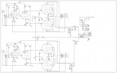
How's this for s simple circuit?
The amp plays like this. 54 mA through the 7.5K resistor, moved the tube bias to match ~50 mA. No smoke, doesnt go as loud, but works. Should be class A with PP transformer balanced, correct? Thanks for any comment / discussion!
The amp plays like this. 54 mA through the 7.5K resistor, moved the tube bias to match ~50 mA. No smoke, doesnt go as loud, but works. Should be class A with PP transformer balanced, correct? Thanks for any comment / discussion!
Attachments
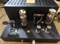
jjasniew, I like the looks of your amp. Clean and simple. But without going through all the posts in the thread, I can not determine what you have inside your EL34 amp. Would you please post a schematic? Is the schematic in post # 24 a reasonable representation of your circuit? If so, what is the topology of your EL34, Triode Mode, or Pentode Mode? (Your amp seems to be quite different than the OP 6L6 with push pull transformer, that is used in a "Single Ended" circuit). Thanks!
Last edited:
jjasniew,
In post # 75, I see two EL34s, two 9 pin tubes, and two 7500 Ohm power resistors. The resistors are connected to a couple of 8 pin sockets, between pin 1 and pin 6?
Are the resistors "substituting" for some missing EL34 tubes in what was originally a push pull stereo amp? Did you use pin 6 on the socket, because an EL34 does not connect to pin 6? 7500 Ohms x 54 mA = 405V (at one end of the push pull transformer primary)?
Triode mode on the remaining EL34 per channel would make more sense, because the tube has to drive 7500 Ohms, And the speaker load as it reflects its impedance onto the push pull primary. That would explain the lower volume (gain) and lower power. If the EL34 was in pentode mode, the gain and max power would be even lower than that.
Did I guess what you have?
(It does not seem to be what is in the schematic of post # 77)
Thanks!
Last edited:
- Status
- This old topic is closed. If you want to reopen this topic, contact a moderator using the "Report Post" button.
- Home
- Amplifiers
- Tubes / Valves
- Simple tube circuit transforming push-pull output transformer into single ended one