Yes, but vacuum valves can't.A choke used as a "ccs" can collapse to 0V, and then continue on to more voltage in the opposite direction.
Not really. A SE output transformer is biased up on the curve, and never gets down to zero current. Being in series with a valve, it also cannot pass below zero.A similar result happens with an SE output transformer primary.
All good fortune,
Chris
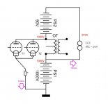
I suspect that what you have drawn is not what you have built.
There are a few flaws in the circuit as drawn. The pinout for the tube is not correct, and there can't be 910 volts coming from the voltage multiplier circuit. If there is, the screen resistor would explode.
A choke used as a "ccs" can collapse to 0V, and then continue on to more voltage in the opposite direction.
Yes it can. That's how the ignition coil in your car works. It's not how an OPT works in a SE circuit.
A similar result happens with an SE output transformer primary.
There is an SE amp sitting on my workbench right now. At idle there is 500 volts of B+ and about 500 on the plate of the output tube. There is actually less due to DCR, but I'm trying to make this simple. The tube is drawing 100 mA of current. All of the operating parameters have been tweaked for perfectly symmetrical clipping, and the amp is driven just to the edge of clipping (maximum undistorted power).
As the grid of the output tube is driven up toward zero the tube current increases and it's plate is pulled toward it's (grounded) cathode. At some point the tube will reach saturation. It can't pull its plate down any further. Let's say its 50 volts. The OPT has 450 volts across it. Attempting to drive the grid further positive will not result in more current flow, or a lower plate voltage, just cause clipping.
As the grid voltage has reached its most positive peak and then turns around the plate voltage will start to rise. At the point the grid voltage reaches it's most negative point, the tube has reached zero current, and any more drive will cause cutoff clipping. Here the plate voltage should be 950 volts. The plate was pulled from 500 volts down to 50 volts, and should swing an equal amount in the opposite direction. The voltage on the OPT is always positive and centered around the B+ voltage.
This is an ideal situation into a resistive load. Things get a bit hairy with a reactive speaker load, and real components. It is possible for the plate to be below zero, but this doesn't happen too often. it is more common for the plate end of the OPT to shoot beyond 2X the B+ voltage. This can happen when the amp is over driven into a speaker near its resonant frequency. Real music imposes transients not seen in sine wave testing.
In the circuit described in the original schematic the PL519 tube has it's plate attached to B+ and its cathode connected through a floating supply to the VT4C's plate. Once that plate flies above B+ the circuit is reverse biased. If the plate is pulled to ground that tube sees a lot of voltage across it.
This might work if the plate of the PL519 is tied to a supply that's 2 X B+ voltage, but that is rather wasteful. Maybe some type of bootstrapping scheme would work.
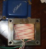
It was easy. No need to de-stack/re-stack the laminations. I just measured the length of wire needed and threaded it thru the winding window turn by turn. "Easy" is assuming there is enough room on the bobbin to get a layer on.
But if one must remove the bobbin for some reason, removing the 4 bolts allows the I lams to be pulled out (and the paper gapping to be removed too).
But if one must remove the bobbin for some reason, removing the 4 bolts allows the I lams to be pulled out (and the paper gapping to be removed too).
...The drawing by PPR is wrong because he is earthing the 519 part....
To PRR: in redrawing my schematic you made a very serious mistake by earthing the floating counter current circuit around the 519. ...
Where have I earthed it? How is my drawing unclear?
Yes, it is AC earthed because you drew the plate of the pentode to the top of the 1000V supply, and I simply rotated.
Attachments
You are right, I was wrong I should have looked better , sorry for this
I've looked at your original post again and saw that all your conclusions were wrong. It doesn't eat half the dc power; it's not working outside it's dissipation (9 watts!).You left out the power transformer and the rectifiers maybe that's the cause of the wrong conclusions.
I've looked at your original post again and saw that all your conclusions were wrong. It doesn't eat half the dc power; it's not working outside it's dissipation (9 watts!).You left out the power transformer and the rectifiers maybe that's the cause of the wrong conclusions.
Chris Hornbeck,
Tubelab_com,
I said:
“A choke used as a "ccs" can collapse to 0V, and then continue on to more voltage in the opposite direction.
A similar result happens with an SE output transformer primary”
The key word is collapse to 0V. I did Not say collapse to 0 current. I was merely pointing out the range of voltage swing of a choke CCS, versus a tube or solid state CCS.
As an example for an OPT primary, I use the following SE amp:
A 2A3 amp can have the following characteristics:
B+ 305V
3k Output Transformer with a primary DCR of 166 Ohms
2A3 plate current 60mA, transformer DCR drop of 10V.
2A3 plate voltage 295V
2A3 self bias voltage 45V.
Now, apply signal amplitude that makes the amplifier output 1.67 Watts.
The Plate lead of the output transformer primary starts at 295V.
The Plate lead of the output transformer primary goes Below 295V on its way to 195V.
Then the Plate lead of the output transformer primary goes back to 295V.
Then the Plate lead of the output transformer primary goes Above 295V on its way to 395V.
That means that the voltage of the primary goes from +, to 0, to -. Without this reversal, an SE amplifier will clip. (and a properly designed 2A3 amp is not likely going to clip when putting out 1.67 Watts).
No, it isn't elegant at all. The small impedance of the 90 V battery shunts the OT's primary. As KeesB says, a high impedance CCS is mandatory.
Best regards!
The CCS was left out intentionally
")
Attachments
It was easy. No need to de-stack/re-stack the laminations. I just measured the length of wire needed and threaded it thru the winding window turn by turn. "Easy" is assuming there is enough room on the bobbin to get a layer on.
But if one must remove the bobbin for some reason, removing the 4 bolts allows the I lams to be pulled out (and the paper gapping to be removed too).
Ah, okay. I was assuming that you removed the gap and re-stacked the laminations in alternating fashion.
It seems like it might be good to just use a smaller gap and the extra winding for flux cancellation. Then, with some small gap still there, the flux cancellation doesn't have to be perfect.
Woops! I posted that last sentence too fast.
The air gap CAN be removed for SE now, since the LV CCS operating the new winding would provide the reverse voltage energy.
I clamped the I lamination pieces down with a big ratchet clamp with rubber jaw pieces while tightening the 4 bolts for the end bells. Re-stacking the lams alternately would increase the inductance further. I forget the exact figures I measured, but the tightened I lams got to within 50% of the normal alternate stacking as I recall. Not too bad, considering the alternate stacked lams are like nearly 100X the inductance of the gapped SE case.
Last edited:
...You left out the power transformer and the rectifiers maybe that's the cause of the wrong conclusions.
I keep looking at your original drawing and I believe it says "910 VDC" across the capacitor feeding the pentode.
I agree I did not initially work-out how 40VAC became "910 VDC". Looking back I see this is unlikely, even if the voltage multiplier were more elaborate than drawn. But ~~1000V seemed a likely counter-voltage for the 1000V triode supply. Unwisely, I relied on the stated "910 VDC" rather than work-out all the details.
Woops! I posted that last sentence too fast.
The air gap CAN be removed for SE now, since the LV CCS operating the new winding would provide the reverse voltage energy.
I clamped the I lamination pieces down with a big ratchet clamp with rubber jaw pieces while tightening the 4 bolts for the end bells. Re-stacking the lams alternately would increase the inductance further. I forget the exact figures I measured, but the tightened I lams got to within 50% of the normal alternate stacking as I recall. Not too bad, considering the alternate stacked lams are like nearly 100X the inductance of the gapped SE case.
Yeah, I can't see an easy way to make the circuit in the OP work in both directions from the output tube quiescent point. However, this added winding could accomplish the same thing with a simple circuit. You just have to find a transformer that has a little extra space for some more wire.
I looked at that 40V too & simply figured it was meant to indicate the PT ran both the 40GK6 heater but another wdg on the same PT got the 910V thru the tripler. Figured that detail got left out of the dwg.
But with only 56V (40V peak) tripled on load might get 140V on the 40GK6 plate there is nowhere to go when the VT4Cs get going. Read compliance.
The separate wdg at low Z looks a solution, avoiding HV.
But its a lot of cct & still needs to dissipate a lot of heat. As well as an extra PT & some semi's.
Maybe the "best" way to do SE with a P-P OT would be to use the more conventional P-P tube pair (class A), but instead of just using the 2nd tube (high Zout pentode) as a fixed CCS, it should still be driven in conventional P-P (opposite phase) mode.
The 2nd "variable CCS" tube could be driven more linearly using grid 2 drive (or even "Crazy drive) to keep it from adding sound effect. As long as the primary "SE" tube has lower Zout than the load or the "Variable CCS", it should be defining the overall sound and damping factor. Twice the signal current now so 4X (? or 2X) the power output, without wasting CCS power, I think. Hopefully still sounding like the SE tube. The variable CCS assist should also be doubling the load Z seen by the active SE tube. Not quite as good as the 4X Zprimary from using the full winding.
The 2nd "variable CCS" tube could be driven more linearly using grid 2 drive (or even "Crazy drive) to keep it from adding sound effect. As long as the primary "SE" tube has lower Zout than the load or the "Variable CCS", it should be defining the overall sound and damping factor. Twice the signal current now so 4X (? or 2X) the power output, without wasting CCS power, I think. Hopefully still sounding like the SE tube. The variable CCS assist should also be doubling the load Z seen by the active SE tube. Not quite as good as the 4X Zprimary from using the full winding.
Last edited:
I ran a whole series of tests on the simple cct using the two tubes in that pseudo PP hookup a couple of years ago. Tried the original cathode resistor, choke & NFET as the tail. Used a pair of 6V6s & a Hammond 125E OPT.
Overall the best results were using a choke tail. But none of the tests resulted in much more than half the power available when driven by an ordinary phase splitter.
That kind of cct has been played with since the beginning of time, I found one dating from WW2. And another in the 50s.
Performance results claimed are all smoke & mirrors. And poor hearing, what my mother used to call a 'tin ear'.
Attachments
“A choke used as a "ccs" can collapse to 0V, and then continue on to more voltage in the opposite direction. A similar result happens with an SE output transformer primary”
I mistook what you said, or more correctly, assumed where the cold lead of your scope probe was. We are saying exactly the same thing, only all my thinking was referenced to circuit ground, or the negative side of the main B+ supply.
Either way this circuit as drawn, or how we think it is drawn, will be reverse biased and ineffective for a good part of one half cycle.
Tubelab_com,
I apologize, it was not very nice of me to pull everyones brain thinking modes away from this thread's 2 tube modes, over to the Parafeed and SE modes.
But I think there are a few out there who do not understand the parafeed choke, and SE OPT transformer models, and what actually happens in those circuits.
P.S. I used to support companies that designed and built RF amplifiers for Base Stations and Cell Phones. Lots of great technology and genius guys there.
A few of my amplifier customers only cared about occupied bandwidth and alternate channels. They did not care about EVM. I told them that the designers of the system for Base and Cell were going to require them to do that measurement too. The amp designers found out soon enough, suddenly needed to measure EVM.
Last edited:
- Status
- This old topic is closed. If you want to reopen this topic, contact a moderator using the "Report Post" button.
- Home
- Amplifiers
- Tubes / Valves
- Simple tube circuit transforming push-pull output transformer into single ended one