Hello,
I am pretty much a newb when it comes to a lot of this stuff so I am looking for a little help from this community. I have built some simple amps like a tripath 2024 and an Nelson Pass ACA as well as some guitar pedal kits so I kinda can understand what is going on in there but I am self taught and pretty new in this journey so it is at a high level.
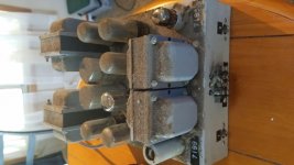
I recently found a sweet score at a yard sale. It is a small stereo tube amp that was hand built as an audio amplifier to provide sound for a real to real movie projector, (from what i was told). I was in too much of an excited state to ask if there was any other components before I left so it is the only piece I have.
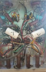
I got her home and opened it up and was very happy to see the guts. Point to point wired with what looks to be quality components. not to mention the tubes are all RCA's, (grey plates?). I am hoping to learn more about this amplifier and either utilize it as an audio amp in my home, or make a couple of guitar amps out of it.
I am looking for help identifying the kit or design/schematic of this amp to learn more about it, decide what it would best be used for, and best steps to get it running. I have started to document the parts/configuration and am going to try and draw out the schematic on paper to help with the learning process.
For now this is what I have.
Each channel has:
1 x 5Y3GT rectifier tube
1 x 7199 preamp/phase splitter?
2 x 6V6GTA power tubes
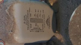
Individual input and output transformers, (will post info on these soon.)
Amplifier has:
No power switch, no volume/tones controls.
Only signal in, signal out and a power cord basically.
I will add more information as well as pictures as time allows.
Thanks in advance for any help!
I am pretty much a newb when it comes to a lot of this stuff so I am looking for a little help from this community. I have built some simple amps like a tripath 2024 and an Nelson Pass ACA as well as some guitar pedal kits so I kinda can understand what is going on in there but I am self taught and pretty new in this journey so it is at a high level.
I recently found a sweet score at a yard sale. It is a small stereo tube amp that was hand built as an audio amplifier to provide sound for a real to real movie projector, (from what i was told). I was in too much of an excited state to ask if there was any other components before I left so it is the only piece I have.
I got her home and opened it up and was very happy to see the guts. Point to point wired with what looks to be quality components. not to mention the tubes are all RCA's, (grey plates?). I am hoping to learn more about this amplifier and either utilize it as an audio amp in my home, or make a couple of guitar amps out of it.
I am looking for help identifying the kit or design/schematic of this amp to learn more about it, decide what it would best be used for, and best steps to get it running. I have started to document the parts/configuration and am going to try and draw out the schematic on paper to help with the learning process.
For now this is what I have.
Each channel has:
1 x 5Y3GT rectifier tube
1 x 7199 preamp/phase splitter?
2 x 6V6GTA power tubes
Individual input and output transformers, (will post info on these soon.)
Amplifier has:
No power switch, no volume/tones controls.
Only signal in, signal out and a power cord basically.
I will add more information as well as pictures as time allows.
Thanks in advance for any help!
Attachments
Last edited:
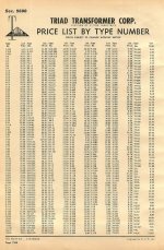
Sounds a lot like a ST70:
Dynaco Dynakit Stereo 70 (ST70) Tube Amplifier Schematic and Manual
But with 6V6GT output tubes.
Dynaco Dynakit Stereo 70 (ST70) Tube Amplifier Schematic and Manual
But with 6V6GT output tubes.
That looks like a competently done build. Nice find!
Can you trace out a schematic? That will help you figure out what the circuit is, and from that you can see if you'll want to change anything.
7199 with PP 6V6 strongly suggests a circuit similar to the Dynaco Stereo 70 amplifier. This amp is probably somewhat simplified, since the Dyna ST70 had some frequency compensation RC networks added in its feedback loop, which you're not as likely to find in a hobbyist-built amp. But that's not 100% certain.
Do you have a variac?
The amp uses old-style parts that may not be working well now. It's probably best to pre-emptively replace the electrolytic capacitors, paper-dielectric capacitors and carbon composition resistors that are likely to have gone bad or out-of-spec. Those old electrolytic 'can' capacitors are undoubtedly dried out and probably leaking DC. Paper caps are often leaky too, causing hum in the output. Carbon comp resistors are likely to have drifted far from their original resistance values, and probably are noisy as well. Replace caps and resistors with modern parts of the same value if you want to run the amp safely. I'd replace the electrolytic caps with newer, smaller ones, the paper capacitors with polypropylene or other plastic film type, and the carbon comp resistors with metal film as appropriate. The big brown wirewound resistors (7500 ohm and 250 ohm) are probably fine (they're pretty indestructible if not overheated).
It looks like that amp will be well worth refurbishing. I hope it works out great for you.
--
That looks like a competently done build. Nice find!
Can you trace out a schematic? That will help you figure out what the circuit is, and from that you can see if you'll want to change anything.
7199 with PP 6V6 strongly suggests a circuit similar to the Dynaco Stereo 70 amplifier. This amp is probably somewhat simplified, since the Dyna ST70 had some frequency compensation RC networks added in its feedback loop, which you're not as likely to find in a hobbyist-built amp. But that's not 100% certain.
Do you have a variac?
The amp uses old-style parts that may not be working well now. It's probably best to pre-emptively replace the electrolytic capacitors, paper-dielectric capacitors and carbon composition resistors that are likely to have gone bad or out-of-spec. Those old electrolytic 'can' capacitors are undoubtedly dried out and probably leaking DC. Paper caps are often leaky too, causing hum in the output. Carbon comp resistors are likely to have drifted far from their original resistance values, and probably are noisy as well. Replace caps and resistors with modern parts of the same value if you want to run the amp safely. I'd replace the electrolytic caps with newer, smaller ones, the paper capacitors with polypropylene or other plastic film type, and the carbon comp resistors with metal film as appropriate. The big brown wirewound resistors (7500 ohm and 250 ohm) are probably fine (they're pretty indestructible if not overheated).
It looks like that amp will be well worth refurbishing. I hope it works out great for you.
--
Thanks,
It does look to be built by someone with decent skills.
I am going to try and trace out the schematic as well as get better pics. I just was excited about all of it and wanted to get my thread started ASAP.
The ST-70 is what I came up with as well in a quick search but there is a lot missing in my amp in comparison. also seems similar to the circuit for a small Fender amp like the Harvard, (5F10).
I do not have a variac.

Is there a way to test the old components to see if they are within spec before removing them? I would like to keep as many of the old parts, (that are safe) as possible, (at least until I learn more and figure out how i want to use it).
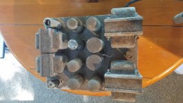
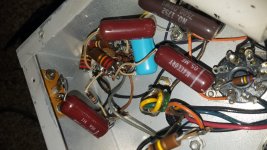
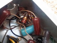
A lot of the parts are a bit older and even with my experiences looking into old guitar tube amp internals some of the components look foreign. The big brown wire wound resistors? Those are the 4 cylinders at the bottom of the picture?
Thanks,
The big brown wire wound resistors? Those are the 4 cylinders at the bottom of the picture?
The brown cylindrical parts that say "OHMS 250" are 250 ohm wirewound resistors.
The brown cylindrical parts that say "7500 OHMS" are 7.5k ohm wirewound resistors.
--
PP 6V6s are good for roughly 15 WPC. The power section of the Dyna SCA-35 will be closer than the Dyna ST-70 to what is actually present.
The SCA-35 uses the high gain pentode voltage amplifier to make up for the tone control losses. Such high gain also makes sense in the reel to reel playback situation, but it's excessive in combination with a "standard" 2 VRMS CDP. Switching to the all triode small signal ST-35 style setup is probably indicated.
The SCA-35 uses the high gain pentode voltage amplifier to make up for the tone control losses. Such high gain also makes sense in the reel to reel playback situation, but it's excessive in combination with a "standard" 2 VRMS CDP. Switching to the all triode small signal ST-35 style setup is probably indicated.
Last edited:
The SCA-35 uses the high gain pentode voltage amplifier to make up for the tone control losses. Such high gain also makes sense in the reel to reel playback situation, but it's excessive in combination with a "standard" 2 VRMS CDP. Switching to the all triode small signal ST-35 style setup is probably indicated.
Not sure I understand much of this, but it gives me things to look up, thank you.
I should be clear that the tubes that I listed were per channel so double up the numbers when looking at the picture.
Also there are separate input and output transformers for each channel. Does this make them more like two mono's in one chassis? it looks to me that they are pretty independent maybe sharing some grounds. Forgive me if I am saying it wrong or not making any sense, I am guessing and going off what little I have absorbed so far.
Last edited by a moderator:
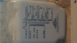
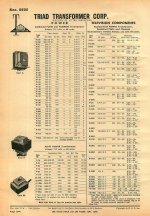
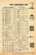
Triad "iron" of that "vintage" is fine. The stuff shown in the photos is (IMO) slightly undersized for 15 WPC. FWIW, I'd like 25 W. capability O/P trafos, in combination with a GNFB loop.
6F6GT is a sweet sounding output pentode that would work better within the limits of those OPTs, right?
Or maybe 6K6GT?
6Y6GT?
Perhaps rather than aiming for getting 15W output per channel from those 15W-rated OPTs, aim for maybe 8W with a little headroom?
--
I did some homework last night and think I understand what a Ground Negative Feedback Loop is now.
If I am looking at it correctly it seems like the output transformers orange wire is the one providing the loop. Looking at the transformer it shows it to be 16 ohms along with a gray wire going to speakers with an 8 ohm load. Does that all make sense and sound correct?
Also I did a lot of searching and would like some help with the components in the picture. I believe it is a (red molded?) MALLORY .05 MF filter capacitor? If anyone can explain what they are, what they do, and when they were made/used I would be grateful. I can look stuff up but need to be pointed in the right direction.
Working on a schematic but I want to try and understand at some level each component and what it is doing as I draw it up.
I am getting more excited as I dig into this project, I spent some time cleaning everything up last night and it appears to be in amazing condition. Also as a guitar player that loves vintage Fender amps 6V6’s are one of my favorite tubes.
Thanks again for everyone’s help and feedback!
Attachments
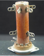
I cannot find a diagram to figure out how a 9 pin Vector tube socket works. I managed to find a picture of one but that's all. The ones in my amp are tightly covered in resistor and capacitors, it's hard to make out much. Any help or ideas would be great help.
Attachments
Last edited:
Also I did a lot of searching and would like some help with the components in the picture. I believe it is a (red molded?) MALLORY .05 MF filter capacitor? If anyone can explain what they are, what they do, and when they were made/used I would be grateful. I can look stuff up but need to be pointed in the right direction.
Those are probably not 'filter' capacitors per se, but rather interstage coupling capacitors, blocking DC from the plate (output) of one stage to the grid (input) of the next. 0.05uF would be a pretty standard value.
Those red Mallory caps are probably metal foil with paper dielectric in a plastic casing. They don't hold up very well over the decades, but they could still be OK.
--
- Status
- This old topic is closed. If you want to reopen this topic, contact a moderator using the "Report Post" button.
- Home
- Amplifiers
- Tubes / Valves
- What is this? 7199/6V6GTA/6V6GTA/5Y3GT