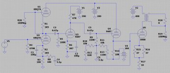
Hello, would like to build this 300B SE tube amplifier. The circuit is said to work fine, taken from a serious book, but first I would like to run a simulation on LTspice. Uploaded the LTspice project along with the tube models, output transformer model .SUBCKT and .asy symbol.
The simulation runs with apparently no errors, but I can see that the first stage has not enough gain and finally there is a very small signal over the output transformer output primary and secondary.
Some notes about the proposed simulation:
1. I am not a simulation expert, and I manage to run analog simulations regularly, but I am a newbie to tube simulations. Yes I have experience in electronics and built a couple of simple tube amplifiers.
2. the tube models used are taken from Mr. Ayumi Nakabayashi's model collection, and I have used them without problems, except for these 3 tubes that are here for the first time. I have edited Mr. Ayumi Nakabayashi's models to work fine with LTspice, in which the '^' operator has been replaced by "**" in al expressions. This was originally designed for TINA simulator, but after this syntax correction it works fine now for LTspice.
3. I managed to implement an output transformer using the model I found here: Dmitry Nizhegorodov . Correction of the original different parameters has been done to match the values of the Lundahl model LL1623 transformer.
4. I included a 100 MOhm R20. Without it LTspice complains about an open node. I also did with R19 that references the output transformer secondary to ground.
5. R10 and R11 are replacing an adjustment potentiometer.
6. I have included the Xfmr.asy that should be copied to correspondent the LTspice program model directory. In my case it is located at c:\Users\Bob\Documents\LTspiceXVII\lib\sym\Misc\
Could you please help me to make this simulation run, and sorry for any errors that you may find.
Kind regards
Attachments
Done nigelwright7557, and it worked ! 21 W output. 11 W output RMS with 100K feedback resistor. Thank you. I think this should be a much "standard" value for a FB resistor. Could be a typo.
MarekH, yes, I use this K coupling factor if I pick individual inductors from the menu, but in this case the transformer follows a model. You can see the model in the link I included in my first post.
The coupling is stated as:
KALL LP1 LP2 {1-1/(QFCTR)} ; COUPLING
Thanks
MarekH, yes, I use this K coupling factor if I pick individual inductors from the menu, but in this case the transformer follows a model. You can see the model in the link I included in my first post.
The coupling is stated as:
KALL LP1 LP2 {1-1/(QFCTR)} ; COUPLING
Thanks
Last edited:
The current feedback resistors give a gain of 1.8 which is nothing. I would try making gain at least 10 and see how you get on.
If you follow your signal through it looks to me like you are using positive feedback. I think its confusing the simulation.
The feedback circuit is right just wrong component values. The feedback signal is in phase with input so it raises the cathode when positive feedback. I simulated it just convince myself. The gain of amp is feedback resistor divided by the 150R. With 1k5 feedback resistor you get a gain of 10. Adjust to suit your needs.
Thank you Nigel, I will experiment with several values. And if it is working with positive FB it could be confusing the simulator, I agree. Is positive FB OK here?
I think that fortunately the output transformer model seems to be working right, which is good news for me because it was hard to figure out a reasonable model myself for this component.
I think that fortunately the output transformer model seems to be working right, which is good news for me because it was hard to figure out a reasonable model myself for this component.
The circuit is said to work fine, taken from a serious book
Are you sure?
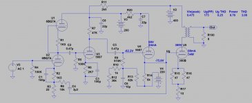
IMHO 5687 and 300B operating points are totally wrong.
The 300B dissipation is over 40W, the 5687 operating point results limited headroom and increased distortion.
Attachments

- Status
- This old topic is closed. If you want to reopen this topic, contact a moderator using the "Report Post" button.
- Home
- Amplifiers
- Tubes / Valves
- Problem simulating SE 300B tube amplifier