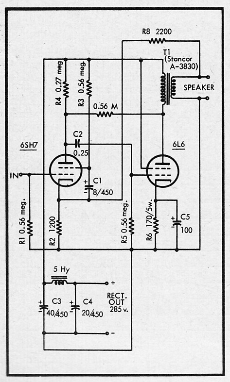
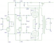
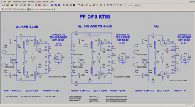
Since we're discussing shunt feedback and the RH84 came up, I've been curious about this amp (see picture) that uses a 6SH7 and a 6L6 but also use the shunt feedback (plus global, which RH84 lacks). One of the attractions is the pentode in the signal stage for higher output impedance vs the 12AT7 in the RH84. From the looks of the schematics it appears to be quite old, possibly from a book or magazine. Does anyone know where it is from? I'd like to read the accompanying text. I'm thinking of building something similar at some point in the near future.
That Schema originally appeared in Audio Magazine in the 1950s.
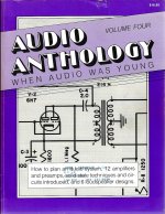
Later it was reproduced by the editor of Glass Audio Magazine along with another PP amp in the Audio Anthology series.")
In my library here somewhere, the Audio Anthology series contains 6 volumes of 8 1/2 x 11 inch pages. A collection of articles from the 50s.
The advantage of the pentode driving is that it is a current source, a much better solution for this type of NFB than a triode.
The original schema of this thread is called 'Anode Follower' in many engineering texts from that era.
Later it was reproduced by the editor of Glass Audio Magazine along with another PP amp in the Audio Anthology series.
In my library here somewhere, the Audio Anthology series contains 6 volumes of 8 1/2 x 11 inch pages. A collection of articles from the 50s.
The advantage of the pentode driving is that it is a current source, a much better solution for this type of NFB than a triode.
The original schema of this thread is called 'Anode Follower' in many engineering texts from that era.
No Sooner Done Than Said!!
The original article was in Audio Magazine August 1955.
The Audio Anthology Series was printed in 1991 by Audio Amateur Publications
The original article was in Audio Magazine August 1955.
The Audio Anthology Series was printed in 1991 by Audio Amateur Publications
Attachments
...possible way to apply local feedback to a power stage with fixed bias when the driver's output impedance is low?
Why does "fixed bias" matter?
WHY would you want to *reduce* the voltage sensitivity of a power valve? Power valves need BIG grid signals. Driver THD is often a significant part of total THD, and sticking loss or NFB between driver and power bottle just makes things worse (higher THD) for the driver.
Schade did it, because he was hoping to upgrade Triode power amps and needed to keep things simple or nobody would try the 6L6. If you have a happy power-triode driver, you have more swing than 6L6 needs. The 6L6 doesn't damp. Two resistors gets the power stage gain near a triode power stage's gain and damping in sight of triodes. We have to wonder if this was really better than triodes. However it sold a lot of 6L6es (Schade's unwritten job) and in time designers extended NFB around driver too. Got good power and low THD and high damping. (Better music? The jury is still deliberating.)
Thank you PRR! When it comes to advanced theory I can only do laboratory mouse workarounds. My interpretation is that this type of feedback reduces the input sensitivity of the driver. I was thinking that the power stage still will need the same Vg1 peak to peak plus the current for the feedback resistor. In other words, the driver has to do double duty; VAS and current amplifier. Provide the voltage for the grids (will this be different when feedback is applied?) without current as long as we stay far from class A2, and at the same time provide the current for the feedback resistor, ideally without voltage swing on that.
But then, in an attempt to keep the driver in its linear area we would need a high gm triode with an inevitable low Zout to drive a power tube with rather high Vg1 meaning not the lowest Zin. So a lot of juice would be lost, but how much? Does driver Zout= 1k to power (I to V) stage Zin= 10k has any meaning at all?
But then, in an attempt to keep the driver in its linear area we would need a high gm triode with an inevitable low Zout to drive a power tube with rather high Vg1 meaning not the lowest Zin. So a lot of juice would be lost, but how much? Does driver Zout= 1k to power (I to V) stage Zin= 10k has any meaning at all?
Why does "fixed bias" matter?
<snip>
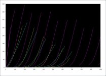
I throw this picture up from time to time. It is KT88 triode curves (blue), 300B curves (yellow), and calculated KT88 pentode w/voltage feedback curves (magenta). The KT88 with feedback curves are 20% feedback, so effective mu is ~5. The KT88 manages to have better linearity, a lower rp, and higher gain than the 300B, and it can be driven to saturation without g1 power drive.
I think a pentode or beam tube can make an excellent replacement for a triode. Of course, there are other grids to deal with and extra components but the curves look nice.
Attachments
From the looks of the schematics it appears to be quite old, possibly from a book or magazine.<snip>
Time to time in old magazines you can find real jewels among a turd, if to know how to spot them.
I throw this picture up from time to time. It is KT88 triode curves (blue), 300B curves (yellow), and calculated KT88 pentode w/voltage feedback curves (magenta). The KT88 with feedback curves are 20% feedback, so effective mu is ~5. The KT88 manages to have better linearity, a lower rp, and higher gain than the 300B, and it can be driven to saturation without g1 power drive.
I think a pentode or beam tube can make an excellent replacement for a triode. Of course, there are other grids to deal with and extra components but the curves look nice.
DIY Audio forum is growing up fast, and I need to figure out something better than Edelweiss-3, while it is not in public domain yet.
Well there is the R
H84 and derivates, build many times.
Mona
From what I see these feedback circuits were used historically on pentodes in a plate-to-plate connection, lowering the final impedance / decreasing distortion and thought well on this type of valve. Pentodes generally have a much higher mu than triodes, so they are ultimately less linear and with less feedback relative to theri internal plate resistance. On triodes they seem less used, because their intrinsic plate impedance is less.
I don't know if my statement is correct, perhaps simplistic, however I was looking for simple examples of triodes where the NFB effect (grid-plate, etc.) makes sense...
6SJ7_6V6 Ampilfier with Internal Negative Feedback
For the curious & others here is a worked example of the plate to plate NFB discussed in this thread. All done with Electronic Workbench vers 5 software which hit the market shortly after the Earth cooled. I got my copy about the time monsters crawled from the sea. It was designed to work in WIN 3.1 & WIN 95. I found it to be OK on up to WIN XP. Recently I loaded the 32-bit vers of WIN 7 into one of my laptops, EWB runs OK with the odd glitch. It is not compatible with a 64-bit OS.
I did these simulations in 2015 out of curiosity. How would this hookup compare with what I’d normally done with a common feedback pair, of which I’d built many with good results.
In the simulations the pentodes are shewn as a voltage controlled current source in parallel with their respective plate resistances. This allows a simple but accurate simulation of small signal circuit performance. Best of all, a wiring error does not result in smoke.
So the constants used are simply for the 6SJ7 Gm of 0.5 mA/V in parallel with 1Meg. And the 6V6 is Gm of 4.1 mA/v in parallel with 52K, all taken from the tube data books.
To get more realistic results I plugged in winding resistances of a real OPT & included 52K in parallel with the primary to simulate iron losses in the OPT core. Not perfect but at least closer to the real thing.
In the sims the Space Bar controls the application of NFB. The Key ‘Z’ is used to disconnect the load. The resulting measurements allow gain of each stage, both tubes & OPT to be included in the results. The OPT changes somewhat when the load is unhooked by Key ‘Z’.
Using the Space Bar to insert the 220K NFB resister into the circuit, the output terminal voltage drops from 2.704V to 0.307V. Stuffing the numbers in & turning the crank on the HP67 shews NFB to be 18.9 db.
We can see the gain of the 6SJ7 dropped from 38.4 to 4.897. The NFB controls the gain of the tube to which it is applied. The gain of the 6V6 changes very little. If the output at the loaded were adjusted to the original level (2.704V), the 6V6 gain would be the same as originally. Key ‘Z’ allows unhooking of the load. Ordinarily in a pentode cct this would result in a very large voltage at the output terminals. But in this case the NFB keeps the output to 0.443V.
Gain of the 6SJ7 is reduced again, this time to ~1.11. The gain across the OPT also changes, the voltage drop in the windings has decreased, the secondary to zero.
With this final indication of output voltage with no load & the earlier indication with both load & NFB connected an estimate of internal AC resistance of the amplifier can be calculated. Rint is delta E / delta I Ohms Rint = (0.443 / 0.3073) / (0.3073/ 8) Ohms Again plugging the numbers into the HP67 the Rint = 3.53R
A better OPT would reduce this number. And Damping Factor for this cct is ~8 / 3.53 = 2.26 About the same as a typical SE triode amp. The cct would benefit from a better driver such as 6AU6/6SH7. Somebody check my numbers!! Pls
Attachments
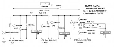
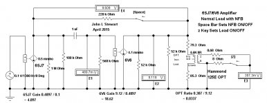
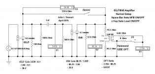
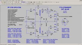
Plate to grid N Fdbk receives another hidden benefit beyond what the usual N Fdbk and loop gain formula would indicate. This comes from the sensitivity of the N Fdbk injection point tracking (non-linearly) the non-linearity of the distorting device in such a way that further correction is achieved for free. When the device current goes up, its gm increases, causing the output Rp to decrease but also the input sensitivity to correction to increase similarly.
Output stage CFB also achieves this extra benefit.
For a TWO stage (driver and output stages) P-P design, with N Fdbk around them both ("local" ie, not passing thru the OT) a similar benefit can be obtained by "crossed" N Fdbks back to the driver grid1's. (or even to the driver grid2's if precautions are included for grid 2 impedance variation)
An example of this is ThorstenL's amplifier design (below) (Which incidentally lowers the input impedance to the driver stage grids, similar to shunt Schade. So a current driver pre stage is needed to drive it. )
https://www.diyaudio.com/forums/tub...tail-distortion-signature-2.html?#post5842600
Crossed N Fdbks have often been touted as cancelling odd harmonics better
than the usual non crossed N Fbks (back to driver cathodes). This can be true IF the scaling of the driver is correctly done. The driver must be operating over a similar portion of a similar non-linear device curve as the output device is. (usually not designed specifically to do this, but could be done) The driver needs to have similar curvature features as the output device obviously.
If this scheme could be done perfectly, (matched similar driver and output tubes and matching non-linear regions of operation) then the output stage distortion could be completely corrected with a -finite- amount of N Fdbk. Practical considerations mean this only partially approaches that ideal, but can exceed the N Fdbk - loop gain formal expectations. A conventional "linear" global N Fdbk around all can iron out the remaining residual distortion.
Attachments
Last edited:
addendum:
Making the driver stage distort similarly (and with crossed N Fdbks) like the output stage also injects further distortion into the forward path. Not good.
But if the input signals to the driver stage were to be inserted at the more linear driver screen grids, then the N Fdbks to grid 1 would still get the enhanced correction for fixing the output stage (tracking non-linearity) while the input signal would not be further distorted by the drivers.
This leads to an amplifier that would likely need pentodes (or similar, cascode, Mu follower ...) every where for gain (well, except not necessarily for the outputs), which would be rather unusual.
I haven't ever considered this topology before, although I see someone used a screen driven driver for an 845 amplifier:
Try A Screen Driven Driver Stage Article By Rikard Berglund From Sound Practices Issue 8, Winter 1994/1995
Makes me think: 6GF5 drivers, 6GE5 outputs. Matched non-linearities. (should work for most any TV Sweep tube outputs, they all are just scaled up versions of 6DQ6, 6GE5/6JN6 anyway. )
Last edited:
magic, looks like a pentode on your schematic, so you don't have an UL transformer?
With UL there is absolutely no reason to connect the grid of the output to its anode with feedback.
PRR said it too, if you want to waste some gain and linearize the output with local feedback, if UL is not enough or not a possibility, you use cathode feedback through a dedicated winding or through the 16 ohm tap if you are in SET. In push pull you need dedicated CFB windings.
Usually GNF is the best solution, but the CFB helps the output drive Z, you reduce GNF by the same ratio...
Scenario, the amp works with 15 db feedback, you install a CFB transformer with 4 db feedback, you reduce GNF by 4 db.
Last edited:
If you look at the curves SpreadSpectrum posted for KT88 shunt Schade (post # 27) versus some UL curves, there is no comparison for linearity. Shunt Schade beats UL hands down, as well as typical $$$ triodes.
Shunt Schade and CFB have the advantage of tracking non-linearity in the N Fdbk path. (series Schade too, need an interstage xfmr though)
Triodes have 3/2 power law at the plate versus 4/2 power law at grid 1. Same thing for UL, 3/2 power law at the screen grid, 4/2 power law at grid 1. Tracking errors.
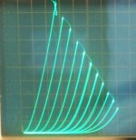
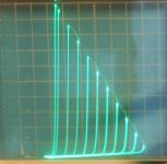
Look at the 6HB6 curves below. 1st pic is g2/g1 triode (like a real triode or UL mode), and the 2nd pic is shunt Schade. Same tube.
Shunt Schade and CFB have the advantage of tracking non-linearity in the N Fdbk path. (series Schade too, need an interstage xfmr though)
Triodes have 3/2 power law at the plate versus 4/2 power law at grid 1. Same thing for UL, 3/2 power law at the screen grid, 4/2 power law at grid 1. Tracking errors.
Look at the 6HB6 curves below. 1st pic is g2/g1 triode (like a real triode or UL mode), and the 2nd pic is shunt Schade. Same tube.
Attachments
Last edited:
With UL there is absolutely no reason to connect the grid of the output to its anode with feedback.
.
Vice verse.
If input goes to control grid, feedback to screen grid, "correction" is much worse that if both input and feedback go to the same grid. Transfer functions when controlling by different grids are different, they do not match.
I built a 100% CFB (follower) SE amp on the bench with and Edcor output transformer and got a 0.6 Ohm output impedance, real-world measurement. Of course, I used a Mosfet as the output device but I don't think a tube would have made that much higher. Once you make a follower amp with an output transformer, the copper losses in the transformer usually dominate the resulting output impedance. The output transformer copper losses account for 0.53 Ohms of that 0.6 Ohms.
I've published driver designs on my blog that can drive follower output stages to clipping with very low distortion.
I've published driver designs on my blog that can drive follower output stages to clipping with very low distortion.
Last edited:
- Home
- Amplifiers
- Tubes / Valves
- Local feedback between grid-cathode