Why you stuck on UL? What's the point?
Reading all those responses I fully agree with Wavebourn's
question!
I never built a pentode amp, this is my first. (well I built 2 CCS with pentodes with great success first try, just a few adjustments, pentodes are very easy to work with)
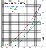
Looking at the pentode curves I assume that the gain mu is higher than in UL
As consequence I could run the amp with GNF(decent amount) + CBF, without overtaxing the poor little 6sn7 LTP.
At worst, I will disconnect the G2 supply which I aim to be around 400V, I never push the amp past 30 watts, and I will keep there the regulated supply for gain and splitter LTP.
I am just afraid that Pentode mode with GNF and CBF wont beat GNF + UL, audibly and in measurements. The bar is very high...
So in the end it is basically a design flaw where the driver is not up to the task. Learning curve...no problem.
When using CFB this has to be taken into account before building anything. Usually CFB windings are in 5-10% ratio so it is not even remotely close to high demand of a cathode follower but it needs careful design nonetheless especially when the sensitivity and/or power level of the output tubes requires significant swing (without CFB already).
When using CFB this has to be taken into account before building anything. Usually CFB windings are in 5-10% ratio so it is not even remotely close to high demand of a cathode follower but it needs careful design nonetheless especially when the sensitivity and/or power level of the output tubes requires significant swing (without CFB already).
45, I am just switching transformers in an old design to test all possibilities. I never intended this amplifier to have a CFB. I purchased the transformers last year for a new project, the mono blocks were built by me 15 years ago.
If there is something that I am learning here it is first, the pentode outputs, which I will see in a few days when I have my G2 fuse, second, that the output transformer quality counts a lot more than I thought.
It was overconfident in UL and GNF to resolve all audible flaws of output transformers. I though a hifi level transformer of good power was sufficient if non-linearities were addressed by global/local, UL, feedbacks. I knew that in SET the quality was paramount, I just didn't thought it would make such a big difference in a push-pull design.
I know that good designs do not use UL, for some reasons, it is always pentode with regulated G2 and regulated G1 bias.
I doubt that it is that good, I will see for myself in a few days, and I have big doubts because I find the sound in UL hard to improve upon, it is quite superb actually.
I am doing this in the perspective of the ultimate amplifier....
A direct zirconium contact input to a 6sn7 frosted, with a high pressure big carbon track mono volume pot, followed with a ecc99 with el822 LTP at around 15ma with over 450V of potential, to the kt120 in UL ( or pentode with CFB) to quads modified exotic super core transformers of around 150 watts, (they already blasted in THD and clearly audible differences my other OTs from 25 to over 100Watts).
The mono block will use a full wave, super high power soft diodes, with film input capacitor, then a 10H 200ma choke, and a 280uf 1000V capacitor to the HV B+.
The bias is regulated from a dedicated transformer with the uttermost quality trim-pots.
The pre sections are all film caps, super high power, regulated 100%. The anode resistors are super huge like 2 inches long, non-inductive super resistors, crazy")
If there is something that I am learning here it is first, the pentode outputs, which I will see in a few days when I have my G2 fuse, second, that the output transformer quality counts a lot more than I thought.
It was overconfident in UL and GNF to resolve all audible flaws of output transformers. I though a hifi level transformer of good power was sufficient if non-linearities were addressed by global/local, UL, feedbacks. I knew that in SET the quality was paramount, I just didn't thought it would make such a big difference in a push-pull design.
I know that good designs do not use UL, for some reasons, it is always pentode with regulated G2 and regulated G1 bias.
I doubt that it is that good, I will see for myself in a few days, and I have big doubts because I find the sound in UL hard to improve upon, it is quite superb actually.
I am doing this in the perspective of the ultimate amplifier....
A direct zirconium contact input to a 6sn7 frosted, with a high pressure big carbon track mono volume pot, followed with a ecc99 with el822 LTP at around 15ma with over 450V of potential, to the kt120 in UL ( or pentode with CFB) to quads modified exotic super core transformers of around 150 watts, (they already blasted in THD and clearly audible differences my other OTs from 25 to over 100Watts).
The mono block will use a full wave, super high power soft diodes, with film input capacitor, then a 10H 200ma choke, and a 280uf 1000V capacitor to the HV B+.
The bias is regulated from a dedicated transformer with the uttermost quality trim-pots.
The pre sections are all film caps, super high power, regulated 100%. The anode resistors are super huge like 2 inches long, non-inductive super resistors, crazy
gabdx: Have you considered using one of these for a cheap and cheerful screen supply?
DC-DC 8-32V to +-45V-390V Step-up Module ZVS High Voltage Capacitor Charge Board | eBay
I have several, if you like I can send you one for 5$ plus postage. Probably the same price as ordering from China, but you'll get it in days, not weeks.
DC-DC 8-32V to +-45V-390V Step-up Module ZVS High Voltage Capacitor Charge Board | eBay
I have several, if you like I can send you one for 5$ plus postage. Probably the same price as ordering from China, but you'll get it in days, not weeks.
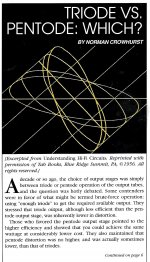
Norman Crowhurst covers all the popular NFB schemes used in the Power stage. This is a very good read.
The comparative qualities of the various ccts is given on p8.
This is a very good read.The comparative qualities of the various ccts is given on p8.
Attachments
-
 Triode vs Pentode Which p1.jpg281.5 KB · Views: 236
 -
 Triode vs Pentode Which p2.jpg723.7 KB · Views: 233
 -
 Triode vs Pentode Which p7.jpg598.9 KB · Views: 130
 -
 Triode vs Pentode Which p6.jpg703.2 KB · Views: 123
 -
 Triode vs Pentode Which p5.jpg319.6 KB · Views: 230
 -
 Triode vs Pentode Which p4.jpg290.6 KB · Views: 225
 -
 Triode vs Pentode Which p3.jpg412.1 KB · Views: 232
 -
 Triode vs Pentode Which p8.jpg696.6 KB · Views: 140
 -
 Triode vs Pentode Which p9.jpg627 KB · Views: 138
 -
 Triode vs Pentode Which p10.jpg702.1 KB · Views: 133
 -
 Triode vs Pentode Which p11.jpg421.6 KB · Views: 129
I would agree on this, I find the UL with proper Z matching is heaven on earth with a quality OT...
It seems that pentode is not the end of the world, contrary to the forum general consensus. However I will try it pretty soon !
Just need to make sure I have all the parts before I place the order to build 2 new monoblocks.
One thing will be different is that I will use 4 power transformer this time. One for power tube bias, 2n for power tube B+ CLC and heaters, 3rd for pentode current sink (-135V supply) and its heaters. 4th is going to supply the new regulated supply to the input tube and LTP ecc99 as well as if required to the control grid in pentode mode.
It seems that pentode is not the end of the world, contrary to the forum general consensus. However I will try it pretty soon !
I don't see anything in Crowhurst's article that shows that Ultralinear is superior to pentode with voltage feedback to the control grid. What did you see in there that contradicts this?
Well, the tetrode cathode follower, Unity-Coupled, and Circlotron are all pentodes with voltage feedback to the grid. They perform much better than UL but it really isn't a fair comparison to UL since there is so much feedback (50% - 100%). A fair comparison would be to construct a circuit with just enough plate-grid feedback to give the same amount of gain as the UL circuit.
I have no doubt that this would give less distortion than UL because you are applying the error correction to the electrode that gave rise to the error in the first place, not some other electrode with other characteristics.
I have no doubt that this would give less distortion than UL because you are applying the error correction to the electrode that gave rise to the error in the first place, not some other electrode with other characteristics.
I have no doubt that this would give less distortion than UL because you are applying the error correction to the electrode that gave rise to the error in the first place, not some other electrode with other characteristics.
Exactly. The name "Ultra Linear" is misleading and is responsible for it's undeserved popularity.

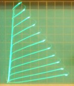
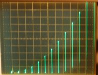
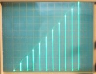
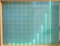
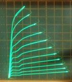
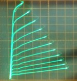
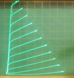
Here are some Vg1 to Ip curve traces for 26LX6 (50 mA per div Vert.)
a) grid 1 drive
b) Crazy drive (grid1 and grid2 special combo) (5.4 V steps)
c) 26LX6 low current end in Crazy Drive (10 mA per div Vert.) (showing low end for class aB overlap)
d) 36LW6 normal plate curves in Crazy drive (50 mA/div) (5 V steps)
e) 36LW6 plate curves for grid 1 drive
f) 26LX6 plate curves for grid 1 drive
g) 26LX6 plate curves for Crazy drive
Ultra linear, hmmm
Attachments
-
 36LW6_Crazy_drive.jpg62.3 KB · Views: 237
 -
 26LX6_Crazy_drive_VtoI_10mA_lowI.JPG293.7 KB · Views: 234
 -
 26LX6_Crazy_drive_VtoI.jpg79.1 KB · Views: 243
 -
 26LX6_grid1_drive_VtoI.jpg82.6 KB · Views: 247
 -
 36LW6_grid1_drive.jpg56.2 KB · Views: 47
 -
 26LX6_grid1_drive.jpg51.4 KB · Views: 45
 -
 26LX6_Crazy_drive.jpg71.9 KB · Views: 44
Last edited:
I just want to point out that in QUAD output stage in the Williamson and Walker paper, the cathode feedback stage also has negative feedback to the screen. So that paper is really comparing UL with UL+CFB. Neither of the output stages examined are Pentode/Tetrode+CFB. If you want to combine Pentode and CFB you have to keep the voltage between screen and cathode constant which requires extra effort in floating supplies or extra OT windings or special cases (like Unity-Coupled config).
To me UL is way superior to UL+CFB,
A great amount of UL is enough and GNF works a lot better to reduce any amplifier parts coloration, reducing GNF and using then CFB corrects only the output stage.
GNF reduces the output Z enough, with UL, so that the CFB is useless and there is no benefits from reducing the output Z more.
To me, with thd levels inaudible, UL was the clear winner over UL + CFB.
However I am curious about pentode + CFB, which will enable same gain levels with a decent amount of GNF.
In other words, the pentode higher gain, plus the CFB plus around same level of GNF is the highest gain, highest feedback solution.
Logically the higher gain, higher feedback levels should sound better, we will see.
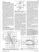
Table 1 in the article refers to stability. this is where pentode is weak.
I am thinking about running the KT120 with a G2 at higher voltage than the anode... regulated.
A great amount of UL is enough and GNF works a lot better to reduce any amplifier parts coloration, reducing GNF and using then CFB corrects only the output stage.
GNF reduces the output Z enough, with UL, so that the CFB is useless and there is no benefits from reducing the output Z more.
To me, with thd levels inaudible, UL was the clear winner over UL + CFB.
However I am curious about pentode + CFB, which will enable same gain levels with a decent amount of GNF.
In other words, the pentode higher gain, plus the CFB plus around same level of GNF is the highest gain, highest feedback solution.
Logically the higher gain, higher feedback levels should sound better, we will see.
Table 1 in the article refers to stability. this is where pentode is weak.
I am thinking about running the KT120 with a G2 at higher voltage than the anode... regulated.
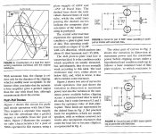
I have a question about shunt P-G feedback. Being my first try I found the LF tightened up. On the other hand midrange lost its charming character (like voices standing out from an orchestra). Is partial feedback possible by dropping simply some HF to ground with C9 and C10?
Attachments
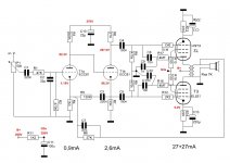
For a start the driver stage is not a balanced cct. The impedance at the driver plate is ~27K while at the cathode much less. Without doing the math about One K.
The results of this modification will be minimal, to the plate NFB by eyeball is only ~1/174. And significantly less to the driver cathode. Surprising you managed to hear any difference at all using that hookup.
Morgan Jones in his book Valve amplifiers suggests using a 'build out' resister on the driver cathode side to equalize the drive. I had a look at that a few years ago & found it just another nuisance that got in the way.
To do this kind of NFB properly it needs to go to a balanced driver. And preferably pentodes. NFB to triode plates increases the drivers distortion.
All covered well in the old EE text books from the 40s & 50s.
C3 & R5 form a +FB path, sometimes used to increase gain.Where did this cct originally come from??
The impedance at the driver plate is ~27K while at the cathode much less. Without doing the math about One K.The results of this modification will be minimal, to the plate NFB by eyeball is only ~1/174. And significantly less to the driver cathode. Surprising you managed to hear any difference at all using that hookup.
Morgan Jones in his book Valve amplifiers suggests using a 'build out' resister on the driver cathode side to equalize the drive. I had a look at that a few years ago & found it just another nuisance that got in the way.
To do this kind of NFB properly it needs to go to a balanced driver. And preferably pentodes. NFB to triode plates increases the drivers distortion.
All covered well in the old EE text books from the 40s & 50s.
C3 & R5 form a +FB path, sometimes used to increase gain.Where did this cct originally come from??
- Home
- Amplifiers
- Tubes / Valves
- Local feedback between grid-cathode