This might be one the the longest project name ever. So I’m starting this new project ! The design have tickled my curiosity, and since I had most of the parts needed on hand I decided to give it a try. I thought I had to do a build thread since it’s a pretty controversial circuit. Everyone that started threads about it were discouraged from building it because no one seems to agree with the original design written in 1949. The results of the original writer were never published, wich seems to add to the controversy. In the end I wasn’t able to find any finished build with actual test results to back up the claims of the original writer. I never performed those kind of tests, but I promise to document the build and to post the results in this thread.
Here is the link to the original article on the diyaudioprojects website:
A Direct-Coupled Amplifier with Cathode Follower by Raymond H. Bates
I’m actually finishing the planning of the layout, and will be drilling the chassis pretty soon. The power supply will be different from the original design since i’ll be using solid state rectifiers and bigger caps, but the i’ll build the input and output stages exactly like the original one. It will be a stereo amp though. The only minor difference is the output transformers DCR, wich is close enough to the specified 250 ohm, but not exactly. From memory, they measure at 230 ohms. The are from antique electronics supply (#pt-31) and costs about 13$ each. I already had a pair from an abandoned project, so they’ll finally get some use.
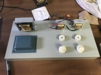
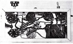
In the picture you can see the layout I chose, the triad choke, tek power transformer and the OPTs.
I’d like to know if you believe the claims of the original writer or not, and why.
Here is the link to the original article on the diyaudioprojects website:
A Direct-Coupled Amplifier with Cathode Follower by Raymond H. Bates
I’m actually finishing the planning of the layout, and will be drilling the chassis pretty soon. The power supply will be different from the original design since i’ll be using solid state rectifiers and bigger caps, but the i’ll build the input and output stages exactly like the original one. It will be a stereo amp though. The only minor difference is the output transformers DCR, wich is close enough to the specified 250 ohm, but not exactly. From memory, they measure at 230 ohms. The are from antique electronics supply (#pt-31) and costs about 13$ each. I already had a pair from an abandoned project, so they’ll finally get some use.
In the picture you can see the layout I chose, the triad choke, tek power transformer and the OPTs.
I’d like to know if you believe the claims of the original writer or not, and why.
Attachments
Last edited:
Not the first time this amp is mentioned. I doubt one can get the claimed 4.5W with that circuit. As the output stage is a cathode follower the input stage has to provide the full voltage. With just over 70V plate voltage I doubt it can do that. In principle it can be done but not this way. The easiest way might be just giving up DC coupling between the two stages.
Quoted from the original article : "With 73 volts at the plate and 55 volts at the screen of the 6SJ7, a voltage amplification of 115 can be obtained at only 0.8 percent distortion. This means that a 0.1 volt signal at the grid of the 6SJ7 will provide a 11.5 volt signal at the grid of the 6V6 which is considered adequate."
If I undersand correctly, most preamps or sources have an output rated between 0.5V and 2.0V. With a voltage amplification of 115, a 2.0V signal would provide 230v at the grid of the 6v6 ? I am no expert of tube data sheets, so i’m not shure how this translate into output power after the 6v6.
The fun part with this is that I wanted to do this to learn a bit more and maybe design a circuit of my own one day. If someone could explain how this works or refer me to the information, it would be much appreciated !
The amplification factor has nothing to do with the maximum swing that one needs to drive the output tube to max power and 11.5V is the swing that is necessary IF the 6V6 is in common cathode. In that case it has its own voltage amplification and so the input stage doesn't need to deliver the full output voltage of the amplifier.Quoted from the original article : "With 73 volts at the plate and 55 volts at the screen of the 6SJ7, a voltage amplification of 115 can be obtained at only 0.8 percent distortion. This means that a 0.1 volt signal at the grid of the 6SJ7 will provide a 11.5 volt signal at the grid of the 6V6 which is considered adequate." <snip>
Having 6K output transformer for 4.5W you need 164V RMS (232V peak) on the grid of the 6V6 which is impossible to obtain from 70V plate voltage of the input tube no matter the amplification factor. The 6SJ7 simply can't swing that voltage. Actually you need about 180V RMS because the cathode follower output stage has a gain a bit less than 1.
With that circuit as is you will barely get 0.4-0.5W. If the 6SJ7 and the 6V6 are RC coupled then you have complete freedom about quiescent conditions of the input tube and can be adjusted to what one needs.
Last edited:
The schematic looked a little odd, so I redrew it.
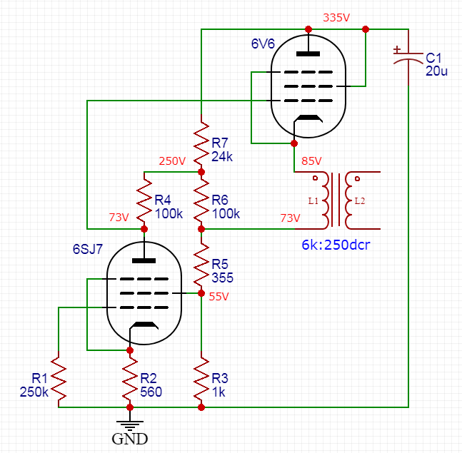
It reminds me a little bit of "NPNCFB" bootstrappy stuff: Neither a pentode nor a Cathode Follower Be
There's some feedback to the 6SJ7 via R3+R5 but it still looks cathode follower-ish in nature.
It reminds me a little bit of "NPNCFB" bootstrappy stuff: Neither a pentode nor a Cathode Follower Be
There's some feedback to the 6SJ7 via R3+R5 but it still looks cathode follower-ish in nature.
Last edited:
Is it possible to drive a cathode follower into class A2. If so, what will be the linearity?
I've never tried...
I honestly cannot answer this question. My manual and the data sheets i’ve looked don’t provide specs for a cathode follower. I don’t have the knowledge to do the calculations/assumptions myself neither.
The schematic looked a little odd, so I redrew it.
<snip>
It reminds me a little bit of "NPNCFB" bootstrappy stuff: Neither a pentode nor a Cathode Follower Be
There's some feedback to the 6SJ7 via R3+R5 but it still looks cathode follower-ish in nature.
It is indeed pretty similar. In fact, that article could be explaining why the author claimed 4-5W : it is in fact not acting like a unity gain buffer. But that also means that the circuit i’m build won’t have, at least, all the attributes of a real cathode follower. If we take for granted that it actually does make it’s claimed power...
I can’t figure out how the author could have design this amplifier while being that wrong about the power figures. Maybe that’s why ! We’ll see!
Is it possible to drive a cathode follower into class A2
Under normal circumstances (linear operation with a common tube) No, it's not possible to reach A2. The cathode will always follow the grid and stay at a potential slightly above the grid (higher positive voltage). Obviously this won't be the case if a tube like the 811A is used that often requires a positive grid voltage to get current flow.
The fact that the grid voltage swing is limited to 85 volts in one direction looks like a limiting factor, but my bet is that it will swing negative due to the inductance in the OPT. How much this will help, I don't know without doing an LT spice sim...or building it.
The think I don't like is the 1355 ohms in series with the OPT. That will eat about 20% of your output power, and kill the damping factor.
The thing I don't like is the 1355 ohms in series with the OPT. That will eat about 20% of your output power, and kill the damping factor.
It might be a dumb question, but why would it hurt more in this context than, lets say, having a 10k plate resistor in a grounded cathode amplifier stage ? The current has to go through the whole circuit anyway, so having a resistance on the plate side or the cathode side shouldn’t affect the power of whole circuit ? (Obviously, If the total resistance stays the same)
I might be getting something wrong but I never saw those resistors as rubbing power from the output
Member
Joined 2009
Paid Member
in common cathode gain stage the 10k resistor you refer to is the load against which the tube works to generate voltage gain. for the output of a power amplifier the output transformer is the load and the voltage developed across it (current) will couple into the load through the secondary winding. A resistor in series with the output transformer will simply waste heat and contribute nothing to the load. But being direct coupled you need to lift the output tube off ground and so you end up needing this resistor.
There is some stabilization of the operating point going on as the cathode of the 6V6 is connected to the screen of the input tube and this feedback to the screen of the input will help linearize it and improve the PSRR.
There is some stabilization of the operating point going on as the cathode of the 6V6 is connected to the screen of the input tube and this feedback to the screen of the input will help linearize it and improve the PSRR.
Last edited:
Not the first time this amp is mentioned. I doubt one can get the claimed 4.5W with that circuit. . .
My sim with similar tubes gives 5.5%THD at 10Vrms across 6K load: 0.016 Watts. 22%THD at 42Vrms in 6k; 0.3W output.
Attachments
A resistor in series with the output transformer will simply waste heat and contribute nothing to the load.
In this case the resistor is not bypassed, so a good chunk of the AC output voltage winds up being burnt up in this resistor too, so it steals power from the load.
Member
Joined 2009
Paid Member
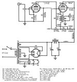
did anybody attempt checking that the schematic matches the wiring in the photo - a thankless task given the poor quality of the photo of course.
Attachments
....If the 6SJ7 and the 6V6 are RC coupled then you have complete freedom about quiescent conditions of the input tube and can be adjusted to what one needs.
AC-coupled, you can do a heap better. Easily 10X the power. Still seriously distorted at any useful power.
My gut says it is not worth tracing the schematic against the chassis photo. A 6V6 as Triode just CAN'T make 4 real Watts SE. (Couple watts at best.) Bates clearly did not METER TEST this amp, just "assumed" it would reach normal-operation output.
Attachments
AC-coupled, you can do a heap better. Easily 10X the power. Still seriously distorted at any useful power.
Yes. With a cathode follower output one just moves the troubles to the input stage and actually it's even bigger trouble. Not so many solutions to get 180V RMS swing with little distortions. If it also has to be cheap even worse..... One needs a good device with its own power supply. That's why that circuit has remained unnoticed and no one addressed those design mistakes.
It is obvious that the original author did not understand his own circuit. If he understood it he would have quietly buried it and felt embarrassed, not published it for everyone to see. Maybe he was drunk when he designed it?
He may have built it and listened to it. A 100mW can sound fine with a high efficiency speaker. I guess he didn't have an oscilloscope.
He may have built it and listened to it. A 100mW can sound fine with a high efficiency speaker. I guess he didn't have an oscilloscope.
I think i’ve had my answer now. The other threads i’ve read about the circuit weren’t as detailed as to why the circuit won’t work or give satisfactory results. They sounded more like haters anything else. Now it’s getting clearer that i’ll be loosing my time building it even though it could be converted into something else easily. Too bad ! I really liked the idea behind it, but too good to be true.
Any ideas for a useful amp that would make good use those parts ? It could be with different valves too. Something like a Single ended el84, el34, 6v6...
Any ideas for a useful amp that would make good use those parts ? It could be with different valves too. Something like a Single ended el84, el34, 6v6...
- Status
- This old topic is closed. If you want to reopen this topic, contact a moderator using the "Report Post" button.
- Home
- Amplifiers
- Tubes / Valves
- DC coupled single ended cathode follower 6SJ7/6V6 amp project