OK, yes I agree. But I thought that saying the extra IM is caused by the collapsing choke inductance is a bit far fetched. I could well imagine an amplifier with high PSRR that is pretty immune to it.
You might as well say that the collapsing inductance increases output power because it will make the average supply voltage to increase.
About the only thing you can say for sure is that the ripple on the supply lines will increase, which is a direct consequence of the lower inductance.
But yes, your reasoning is OK in principle ;-)
Jan
I did some more experimenting. The power tube bypass cap had a slight effect. I tried a few different values, but ended up with 220. I may still go back to the 470, because I think it may have sounded better.
The problem was still there. As an experiment, I hooked up my variac and determined that if I lowered the voltage, roughly 100 volts ac, the problem went away. The bias of the power tubes dropped to around 72 ma, which with the 6sn7, puts it right around the 80 ma of the choke. Then I had to see whether it was the lower voltage or the choke, which prompted me to disconnect one end of the choke and try a 470 ohm resistor.
With the resistor, the problem went away. It was still a bit lower voltage and it didn’t sound as good. There was some slight hum at the speaker. As a final experiment, I clipped the choke in parallel with the resistor. In that configuration, the voltages were just about back to where I wanted them, and the sound seemed almost as good as it was. I can’t help but suspect that slight difference was the different cathode bypass capacitor.
So, it was the choke after all and I believe it was acting as Disco suspected - IMD at loud passages. Thanks so much for the assistance. I’m going to have to buy a better choke, now!
I bought a Hammond 193G, 10H, 150ma, 102 ohms. Then, the plan will is to work a resistor between the diodes and first filter cap to set the voltage.
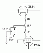
Somewhat off topic, but while I’ve got the attention of some very knowledgeable folks, what are everyone’s thoughts on the two channels’ EL84s sharing a bias resistor? Is that it better to give each tube its own cathode bias resistor and bypass cap?
Somewhat off topic, but while I’ve got the attention of some very knowledgeable folks, what are everyone’s thoughts on the two channels’ EL84s sharing a bias resistor? Is that it better to give each tube its own cathode bias resistor and bypass cap?
Is this a 2 channel amp? I always use a single a bias resistor for each power tube. It is not really necessary, but, in my SE amps i like it that each power tube has its own resistor and bias cap. You need to double the value of the resistor. Bypass cap should be more than 50uf for an el84 but some guys like 100uf.
what ... two channels’ EL84s sharing a bias resistor? Is it better to give each tube its own cathode bias resistor and bypass cap?
The EL84s are in opposite phase, only in theory equally. Connecting both cathodes brings them at the same DC level (which still wanders around in time) what helps for exact and opposite phase reproduction.
Last edited:
In this example a CCS actively regulates the cathode current for the compound of both EL84s. (Forget the pot, it's there to compensate for an unbalanced pair of EL84s.) Arguements in favour of applying this constant current source is to obtain maximal undistorted output power and having unequalled low frequency output. Against is loss of agreeable tone, to which one could listen without getting tired.
Attachments
- Status
- This old topic is closed. If you want to reopen this topic, contact a moderator using the "Report Post" button.
- Home
- Amplifiers
- Tubes / Valves
- Stupid question regarding chokes
