Surely, other things being equal, a 12AU7/ECC82 will drop gain more than noise so the output S/N will be made worse? The 12AY7 (and 12AX7/ECC83) were designed to give high gain and low noise for audio amplification. However, they need to be used properly. The 12AU7 is just two VHF power oscillator triodes (6C4/EC90) forced into the same envelope.
Noise may be a sign of parasitic oscillation.
Noise may be a sign of parasitic oscillation.
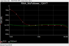
I had simulated and found the 300k to give flat to 0.1db, and on the spec analyzer although not as good was within 0.5db at the bottom end. This using a simulation of my inverse RIAA, though using the standard Laplace was in a gnats breath of that value.
The value of R9 depends highly on the output impedance of the driving stage so I guess it could be down to sim models I’m using Koren GE data book June 1955 for the tubes
The value of R9 depends highly on the output impedance of the driving stage so I guess it could be down to sim models I’m using Koren GE data book June 1955 for the tubes
Okay I think I have fixed it, I went back to first principles, the top tube is a cathode follower, and previous experience had shown that the 12AY7 did not make a good CF so I replaced it with a Mullard CV4024, and now the noise is acceptable, plus still the great sound as all the amplification is still by the 12AY7 thanks for all the responses.
Just to make some more smoke. (and these are back-of-the-envelope calculations!)
The integrated noise of the RIAA network, using SY's approach (see the article "His Master's Noise") of dividing up the audio spectrum 10-100Hz, 100Hz to 1kHz and 1kHz to 10kHz is about 2.5uV over the bandwidth for the 300k network, and about 0.8uV using a value of 40k for the lead-in resistor (R1 in Lipshitz.)
The mu-follower output impedance isn't as low as theory would predict, or at least it as low when it is simulated. Thus the network with R1=40k yields net gain of 6dB at 1kHz while the 300k network almost 9dB with values such that the slope from 20hZ to 1kHz is approximately-20dB.
With a 3mV signal, the SNR of the unit with 300k resistor is 7dB worse.
Can't speak to the noise of the 12AY7 itself. Will have to get a couple and check it out.
Just to make some more smoke. (and these are back-of-the-envelope calculations!)
The integrated noise of the RIAA network, using SY's approach (see the article "His Master's Noise") of dividing up the audio spectrum 10-100Hz, 100Hz to 1kHz and 1kHz to 10kHz is about 2.5uV over the bandwidth for the 300k network, and about 0.8uV using a value of 40k for the lead-in resistor (R1 in Lipshitz.)
The mu-follower output impedance isn't as low as theory would predict, or at least it as low when it is simulated. Thus the network with R1=40k yields net gain of 6dB at 1kHz while the 300k network almost 9dB with values such that the slope from 20hZ to 1kHz is approximately-20dB.
With a 3mV signal, the SNR of the unit with 300k resistor is 7dB worse.
Can't speak to the noise of the 12AY7 itself. Will have to get a couple and check it out.
Thank you for that insight, I was really trying to keep the capacitor values low so I can use silver mica, also the mu follower has problems driving reactive loads, the 300k isolates the mu from the reactance.
I will try to build a low R1 version and see if it will work, however the current version is now acceptable
- Status
- This old topic is closed. If you want to reopen this topic, contact a moderator using the "Report Post" button.
- Home
- Amplifiers
- Tubes / Valves
- Noise in mu follower phono amp