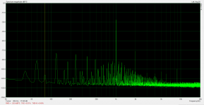
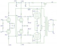
Was looking at this neat little PP amplifier from RCA manual and it got me thinking about the distortion signature if one went PP from stem to stern.

The idea is to use a splitting xformer at the input and use push pull amplification stages each with a touch of local feedback all the way to the output. My understanding of that output-driver stage is that the local FB not only reduces distortion of each phase and lowers Zout but also that it balances the gain between phases contributing to better cancellation of even harmonics generated in that stage.
My assumption is that using a similar technique for the preceding stages (possibly in the form of plate to grid FB) should provide similar advantages all along the way. Is that a reasonable assumption?
So then the big question becomes how would the distortion levels and spectrum compare to a more standard approach of SE up to the driver or output stage? I would assume the HD would be lower but would the proportion of odd order to even order be increased? Also what would be the difference in proportion of remaining higher order (even and odd combined) to lower order by using this PP through and through approach?
Push-pull reduces even-order distortion but leaves odd-order distortion unchanged. It is possible that higher order even-order distortion is not reduced as much as lower orders, because that would require very close matching. Even if you could achieve close matching at first a little ageing of devices would destroy it.
There are reasons why conventional circuits have been successfully used for many decades.
There are reasons why conventional circuits have been successfully used for many decades.
feedback considered good
Neg feedback will give all sorts of good effect on amps, provided it's properly implemented. This is observed by the telecom industry in the 30's and confirmed by modern practice. It will for instance make the individual tube properties unimportant and it will also reduce distortion.
Neg feedback will give all sorts of good effect on amps, provided it's properly implemented. This is observed by the telecom industry in the 30's and confirmed by modern practice. It will for instance make the individual tube properties unimportant and it will also reduce distortion.
There are plenty of "Balanced" designs used in Pro-Audio and studio equipment.... both tube and Solid-Sate...
This can lead to very low noise floors and other reduction of self induced even harmonics...
The ideal situation is to have both DC balance and AC (trans-conductance) balance to be perfect.... Since there is inevitable drift, aging and initial tolerances, cross-coupled feedback is typically implemented to maintain a sense of balance throughout the life cycle...
If you look at the work that SY did, a concertina that is properly implemented driving a high impedance load, will maintain balance irrespective of the active device characteristics.
Not so big a fan of cross-coupled feedback in line drivers since there have been reports of instability driving very long lines in the PA world, but I guess you could be referring to internal architecture where stability can be guaranteed.
Not so big a fan of cross-coupled feedback in line drivers since there have been reports of instability driving very long lines in the PA world, but I guess you could be referring to internal architecture where stability can be guaranteed.
If you look at the work that SY did, a concertina that is properly implemented driving a high impedance load, will maintain balance irrespective of the active device characteristics.
Very old news. The Williamson Amplifier
By inspection, the concertina outputs are well balanced with equal loads. No testing or calculation needed, since Ip = Ik, and the plate and cathode resistors (and loads) are equal.
A truly differential input can help manage the many, many poor "grounding"/shielding schemes in a typical system. Push-pull stages in general both inject less signal into power supply and "ground" wiring, and are less effected by garbage on those wires (class A assumed).
Even amplifiers with single-ended output stages would benefit from differential inputs and improved (two conductors in each channel's shield) interconnection wiring. DIY doesn't have to repeat the errors of the past.
All good fortune,
Chris
Even amplifiers with single-ended output stages would benefit from differential inputs and improved (two conductors in each channel's shield) interconnection wiring. DIY doesn't have to repeat the errors of the past.
All good fortune,
Chris
Tubelab (George) contributed a PP 6L6GC Class AB2 design that used two 6SN7 LTP stages into PP 6L6GC outputs. Worth a look.
6L6GC AB2 Amp
Way back in the 1990s, there was this thing called Tube-o-saurus Rex, using a 6DJ8 LTP DC-coupled to 6SN7 diff driver RC-coupled to PP 6B4G outputs. I built one with 300B outputs and UTC LS-63 OPTs. Turned out pretty well, even though I was a beginner in over my head and made a lot of mistakes.
--
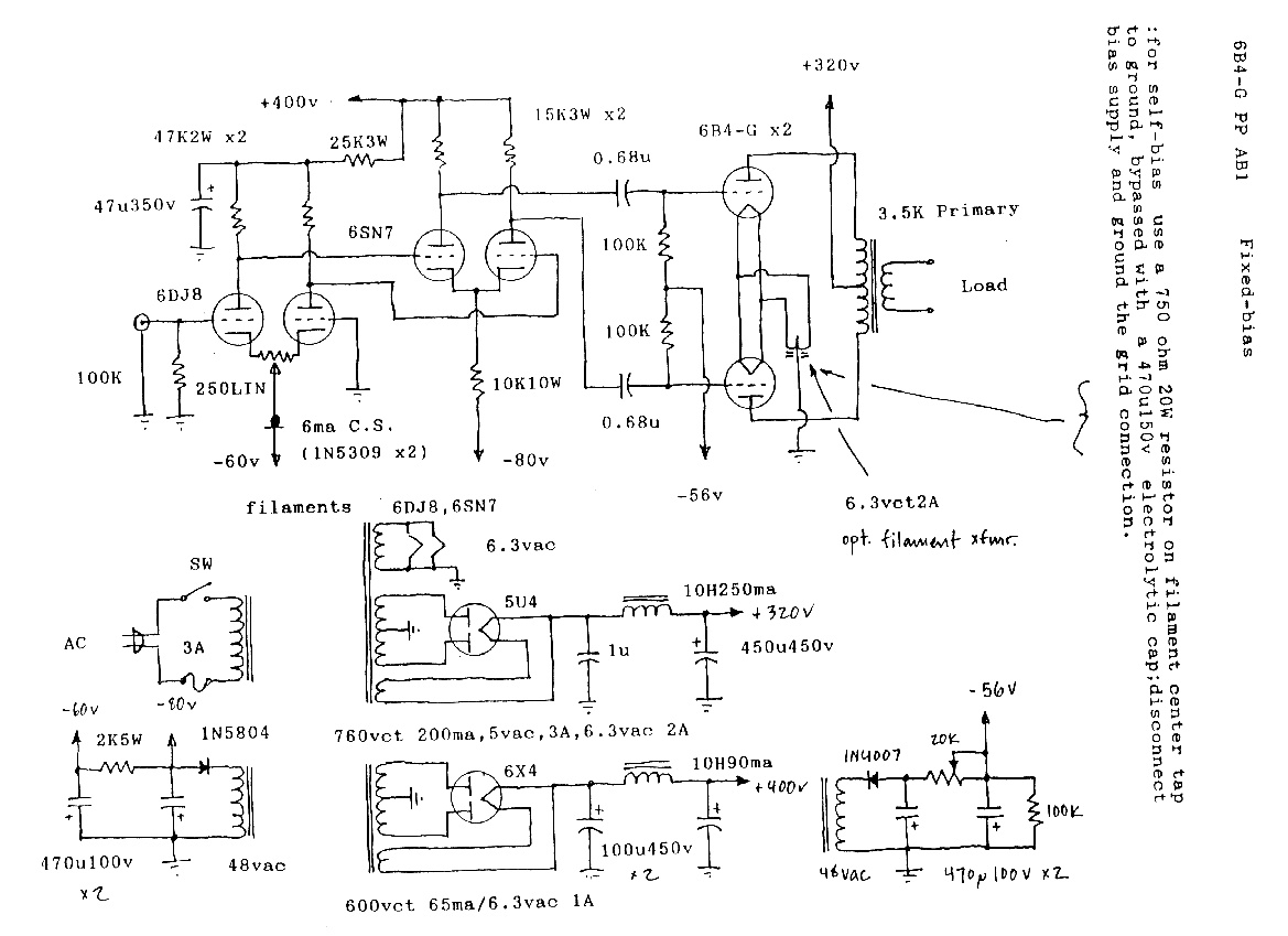
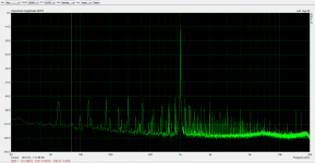
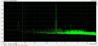
I have built three tube amps, two Push-pull (in a balanced configuration all the way through), and one SE. All three had heavy local feedback in the output stage, and measurements were taken at 1W. All three have no global feedback so comparing them can give an idea of the distortion profiles inherent to the topologies themselves at the same power level. The two P-P amps are capable of 50W and 40W, the SE amp hit 5% distortion at 18.5W, just to give you an idea of relative size/capability.
The third one is the SE amp and you can see it just has a bunch more 2nd harmonic. All three amps have high-order stuff in them, especially when you start going up in power. The SE amp THD stays basically the same from 1 to 10 watts, but you see the high-order products just coming up as power increases until they start significantly adding to the total. 2nd stays remarkably constant with level.
All three amps have high-order stuff that shifts around with level. If you compare at 2W, one amp will look better but if you compare at 3W a different one will look better. These are complex systems and I'm sure that some products cancel at one level but start adding at another level, etc. I wouldn't say that any one of these three amps is significantly better than the others when it comes to high-order products than the others, except to say that the SE creates a lot of really long blades of grass above 10W. It is no longer a waterfall there, whereas the P-P amps maintain that waterfall to higher levels. Makes sense, they are more powerful amps.
Attachments
Last edited:
ThorstenL posted an all differential stage amplifier using crossed N Fdbks that might be of interest (scheme below).
https://www.diyaudio.com/forums/tub...l-fb-decent-damping-factor-4.html?#post478588
Some comments in that thread relate to reduced odd harmonics for crossed N Fdbks, and current Fdbks versus voltage Fdbks (insensitivity to shunt non-linear impedances). This got me thinking (uh-oh dangerous) as to how that might work. The usual local or partial N Fdbks, which are not crossed, connect tube stages with opposite current swings. This provides some 2nd Harmonic cancellation between stages, but typically increases higher harmonics.
The crossed N Fdbks connect tubes which have similar current swings. Now, when one output tube develops low output impedance at high current, the driver tube either develops low input Z (cathode insertion) or higher gm (grid insertion) with higher current. Both tend to cancel ALL harmonics by similarity of forward and backward path non-linearities, IF the driver stage is operating over a similar portion of its operating (current) range as the output tube. (ie, matched non-linear transfers for both stages) (NOT commonly the case, but could be arranged for by design) Just something to think about for an all differential design.
-------------------------------
Another unusual differential design is to provide a separate differential driver for EACH output tube, with separate partial N Fdbks. This allows one to do unusual things like make the output tubes (typically power beam tubes) to each emulate one tube in the associated differential pair (maybe a triode function). One needs to get the two path gains matched up so the outputs will not be fighting each other with their (now) very low output impedances (an AC balance adjustment pot).
Attachments
Last edited:
")
Way back in the 1990s, there was this thing called Tube-o-saurus Rex,
using a 6DJ8 LTP DC-coupled to 6SN7 diff driver
You can't direct couple both plates of a tube diff amp to both grids of the next tube diff amp.
The DC conditions just won't work. Only direct couple one side, and cap couple the other,
with a 1M resistor from the cap coupled grid to the input stage other side's plate.
In this way, the second diff amp has exactly the same DC on both of its grids.
This coupling circuit was used by Luxman, etc.
Last edited:
Somethings I am not clear on is what sets the feedback level in Thorsten's amp (the ratio of feedback resistor to the 6SL7s anode load resistor?) and also in what sense it is current feedback.
I think it would be called current feedback (just the means of the V feedback, not some monitored current) if both the input signal and the Fdbk signal are relatively high impedances which are trying to hold some node voltage constant. (if infinite loop gain) Obviously the node at a grid still needs to develop some drive voltage for the next stage. Thortsten mentioned that the 6SL7 was acting as a modulated current source with high output Z ( degeneration in the 6SL7 cathode)
If the drive signal and Fdbk signal are relatively low impedances (with respect to nodes) then it would look like voltage Fdbk. Typically drive signal to hi-Z grid, and N Fdbk to cathode with degeneration R. The two nodes try to track each other, but some difference remains to drive the stage.
For Thorsten's crossed Fdbks, the ratio of the 820K to the 6SL7 plate resistor in parallel with the 6SL7 (k degenerated, increased) plate Z is setting the ratio.
---------
'you would need in such cases tubes with transfer functions sum of which result in the straight line. I.e. one tube, one anti-tube.
The Fdbk compensation idea just requires the N Fdbk to become similarly more effective (at limiting the output) synchronously as the output device becomes more effective at producing the output (via increased gm, lower output Z)
Ie, the strength of the two opposing forces track each other so as to maintain constant resultant net gain, despite the non-linear variation in the output device gain.
Example:
Say the output device increases in gain by 5% at some current level, and the N Fdbk path similarly increases in strength by 5% (like changing the N Fdbk attenuator for conventional case), then the output can be held constant.
So a --finite-- (matched non-linear) N Fdbk in this case can produce constant net gain. (usually an infinite loop gain would be required for conventional, non transfer tracking, N Fdbk)
Obviously this is an idealized scheme, and real devices won't track so well. So this scheme would be good for an inner loop. The outer loop would then take care of any mis-tracking residual. The semantic attraction here is that a low N Fdbk setup could ideally produce a completely linearized result. The low Fdbk crowd can have their cake, and the high Fdbk crowd can have their linearity. ( so eat the cake)
Last edited:
This is also a good recipe for a big oscillator, so not for the faint of heart.
Yes, taking the N Fdbk signal from the opposite side of the OT from the driven tube (for class AB) (crossed N Fdbks) does set off some stability alarms, since the Fdbk signal has to pass -thru- the OT. (so a possible phase shift issue) This should be OK if there is minimal loading on the Fdbk signal winding. 820K would qualify for minimal loading I think. A differential driver that is monitoring BOTH sides of the OT's primary Fdbks would also improve matters. Apparently, ThorstenL was quite satisfied with his design.
N Fdbks to the driver inputs (grids) also means a lot more gain in the N Fdbk loop around both stages. Stability concerns from higher loop gain of course.
A further improvement could be made by using a Crowhurst Twin Coupled output design, or an Elliptron type design (similar to the Twin Coupled, except the cathodes go to the UL taps on the bottom OT) This way both sides of the OT(s) are always driven, no matter which output tube is conducting. Similar in effect to a Circlotron, except just one power supply.
(of interest: Edcor CXPP25-16-1.6K OT in Elliptron mode, giving a resultant 3.1K primary and 8 Ohm output from the 16 Ohm secondaries paralleled, UL taps giving 28.5% CFB, 50 Watts total rating )
An additional step to reduce the loop gain somewhat would be to take the crossed N Fdbks (from UL taps) back to the driver -screen- grids, instead of grid 1s. This takes some care, since the screen grids are drawing current. Jan Veiset showed how to do this by arranging the N Fdbk attenuation so that the screen grid voltage variation was a constant fraction of the driver output plate signal variation. Then the driver screen intercepts a constant fraction of the driver cathode current and so acts like a linear resistor. Besides the reduced loop gain, the advantage here is that the driver grid 1s remain high impedance for ease of drive from the pre-amp stage. This incidentally makes the output tubes emulate the triode function of the driver tube g1/g2. Of course you now have the most advanced and complicated tube amp to reside on planet #3 !
Last edited:
If you look at the schematic a bit, feel that there's something wrong, but can't quite put a finger on it, it's because your childhood ham radio self is seeing a cross-coupled push-pull oscillator peeking out from the bushes.
The issue isn't with local negative feedback, but rather with keeping the feedback negative. Several points connect the two polarity halves together and mix them, including the constant-current source for the 6SN7 stage and the output transformer. Way too twitchy for me, but someone like Wavebourn could make it work.
For anyone who wants to try this kind of thing, take all precautions to protect your output transformer windings' insulation with steering diodes, Zobels on primary and secondary, etc.
All good fortune,
Chris
- Status
- This old topic is closed. If you want to reopen this topic, contact a moderator using the "Report Post" button.
- Home
- Amplifiers
- Tubes / Valves
- Push pull from nose to tail...distortion signature