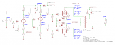
Ketje ->Thank you for the info, I will resolder the board this week. Do you think that the inverted signal is too low to correctly steer power tubes? I measured it and signal has c.a. 14V.
Regarding OT - I have a very trusted source of them because build them by myself") . Due to some reasons, I have access to the workshop with all materials and machines to build transformers with EI core.
. Due to some reasons, I have access to the workshop with all materials and machines to build transformers with EI core.
Even if we consider efficiency at 90% output power should be +- 17*0,9~15W. If you need I can share all the documentation of them.
tikiroo -> what do you mean by "DC couple"? Do you think about removing CX2?
Regarding OT - I have a very trusted source of them because build them by myself
. Due to some reasons, I have access to the workshop with all materials and machines to build transformers with EI core.Even if we consider efficiency at 90% output power should be +- 17*0,9~15W. If you need I can share all the documentation of them.
tikiroo -> what do you mean by "DC couple"? Do you think about removing CX2?
Last edited:
Yes that can be done too.With those voltages (Ketje's adjusted component values) you could dc couple V1A and V1B for improved stability.
Mona
Attachments
My EL84 PP amp puts out a clean, solid 17W/channel.
Simple, proven design, with a unique "servo bias" system that keeps output bias stable even during heavy transients.
12AX7 tubes can be used instead of the 6EU7's with the proper circuit changes.
I also designed in a variable feedback switch to taylor the amp to different speakers, should I ever change them.
Attachments
with a unique "servo bias" system
Have you compared auto bias to fixed bias? Many people find the former better sounding. It's a good thing LM337 adjustment current is only 0,1mA else you would burn out the wiper contact over time.
Have you compared auto bias to fixed bias? Many people find the former better sounding. It's a good thing LM337 adjustment current is only 0,1mA else you would burn out the wiper contact over time.
Essentially, my EL84 amp IS "fixed bias" for all intents and purposes.
If you look at the notations on the schematic, the "EFB" stands for Enhanced Fixed Bias.
This system, designed by David Gillespie, uses the LM337 to control output bias, and "track" any power supply fluctuations that may happen under heavy load conditions, such as like "heavy bass" and such.
The result is that the output tubes won't have a chance to go into saturation and control grid issues, along with substantially less IM distortion.
Comparing my amp "Before" with cathode bias, and now "After" with the EFB system, I can now get more "headroom", more "wattage" (17/per) and substantally longer tube life.
The amp sounds wonderful, clean, and punchy, a joy to listen to, and compares with many of those fancy $3000 to $5000 amps being sold today.
Autobias prolongs tube life I've always understood but hey, there's nothing to be tightass about. Measuring is a good thing to see if the circuit lives up to calculations but then listening begins. That's why I asked about your experience. Creative solution from Gillespie but it compromises safety somewhat as one can loose bias voltage. Enjoy!
If the output use more current the supply starts to go down and so does the bias, resulting in even more current from the output and further drop of the bias end so on ...This system, designed by David Gillespie, uses the LM337 to control output bias, and "track" any power supply fluctuations that may happen under heavy load conditions, such as like "heavy bass" and such.
I suppose the voltage devider to the control of the LM337 has to be large enough to prevent instabilty ?
Mona
If the output use more current the supply starts to go down and so does the bias, resulting in even more current from the output and further drop of the bias end so on ...
I suppose the voltage devider to the control of the LM337 has to be large enough to prevent instabilty ?
Mona
A more detailed and thorough explanation of this "EFB" design is located here.
Good reading, and its implication into my traditionally cathode-biased amp made a world of difference.
http://www.tronola.com/A_New_Look_At_An_Old_Friend.pdf
Hi guys,
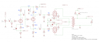
so, I did measure my old circuit and then I resolder and remeasure new one according to Ketje suggestion. Point is, that after the changes, the output power is even lower than before
Does any have an idea? I'm considering rework of the pcb according to the "wiseoldtech" schematics, but with fixed bias (easier for testing).
Attachments
Anybody familiar with Roger Modjeski's RM-10, 35W from a single PP pair of EL84, long tube life expectation and low idling dissipation?
I had heard of it, saw pitctures of it, and at the time was curious how he got 2X the power from a set of EL84's.
I remember some previous threads discussing it, also covered by the designer here:
Re: Power ratings... - Roger A. Modjeski - Tubes Asylum
Re: Power ratings... - Roger A. Modjeski - Tubes Asylum
I found a couple of places Roger himself talked about the design diytube.com • View topic - How many watts from a pair of EL84's? and A TRUE REVOLUTION IN S. E. T. TUBE DESIGN.... I thought many people should have been aware of it since the info was made publicly available for more than a decade. Description of it seems clear enough for DIYer to use the described operating point to use on alternative designs. Could those who tried share difficulties they met on their builds? Any other toughts or comments?
Last edited:
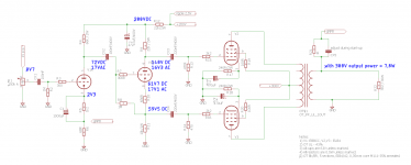
The voltages are looking ok.Hi guys,
so, I did measure my old circuit and then I resolder and remeasure new one according to Ketje suggestion. Point is, that after the changes, the output power is even lower than before
But 7,8W is way to low. Is the Raa of the transformer 8k, that is 2k per side ?
With those things 2k+2k isn't 4k but 8k, so if it is 4k+4k you have a Raa=16k transformer.Could explain half the power.
Mona
- Status
- This old topic is closed. If you want to reopen this topic, contact a moderator using the "Report Post" button.
- Home
- Amplifiers
- Tubes / Valves
- Push-Pull EL84 amplifier