I would like to try two toroids in series as an OPT but I am not sure about the calculations.
See document attached.
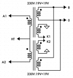
- (230 + 230) / 19 = 24.21 turn ratio
- (24.21 * 24.21) * 8 = 4700 ohms plate to plate for 8 ohms load at secondary.
Is it correct?
PT toroids has often two same secondaries, why not use the other for a little bit of CFB?
Do you think two 50VA's in series will be able to:
- handle 100mA at 200V on each side of the PP
- handle 50Hz at about max 15W
Or 100VA would be better?
Rp will be about 600 Ohms on each side of the PP.
Thank you.
See document attached.
- (230 + 230) / 19 = 24.21 turn ratio
- (24.21 * 24.21) * 8 = 4700 ohms plate to plate for 8 ohms load at secondary.
Is it correct?
PT toroids has often two same secondaries, why not use the other for a little bit of CFB?
Do you think two 50VA's in series will be able to:
- handle 100mA at 200V on each side of the PP
- handle 50Hz at about max 15W
Or 100VA would be better?
Rp will be about 600 Ohms on each side of the PP.
Thank you.
Attachments
I think it won't work, in a Push Pull OPT the 2 halves of primary are on the same core so the sum of the DC currents will be close to zero.
Using two distinct toroids in series, since their cores aren't magnetically coupled, won't get DC current null
DC current will cause core saturation
Using two distinct toroids in series, since their cores aren't magnetically coupled, won't get DC current null
DC current will cause core saturation
Last edited:
I was reading about the idea of putting toroids in series here :
3E29 (829B) Push Pull Amplifier
Sorry DF96, i was writing while you replied...
3E29 (829B) Push Pull Amplifier
Sorry DF96, i was writing while you replied...
That unfortunately doesn’t work. There is no way to balance the flux in the “primary”. The two halves of the primary need to be on the same core to do that. The only way it would work would be if the trafos were suitable for single ended operation, and power toroids are about as far from that as you can get.
A 2x115 primary will work, up to about 200 volts peak at 50 Hz, and the smaller VA’s tend to have better frequency response than the big VA’s.
A 2x115 primary will work, up to about 200 volts peak at 50 Hz, and the smaller VA’s tend to have better frequency response than the big VA’s.
You could maybe get around the DC current problem by using a circlotron topology, as in the old electro-voice amplifiers http://circlotron.tripod.com/a30.pdf. Then, there will be no DC on the output transformer primaries. Of course the power supplies needed for a circlotron are a little more complicated.
Thank you all.
Fixed bias and class A only operation may help.
I didn't see the 6P45S thread, he said it works in series but the secondaries are in series too, is it the reason
So a single 100VA 115-0-115 may be sufficient for a few watts at 50Hz and may be "better" if Rp is low
Fixed bias and class A only operation may help.
I didn't see the 6P45S thread, he said it works in series but the secondaries are in series too, is it the reason
So a single 100VA 115-0-115 may be sufficient for a few watts at 50Hz and may be "better" if Rp is low
You could maybe get around the DC current problem by using a circlotron topology, as in the old electro-voice amplifiers http://circlotron.tripod.com/a30.pdf. Then, there will be no DC on the output transformer primaries......
Really??
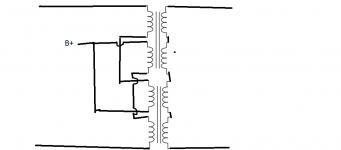
It does work if connected as shown below, sketch courtesy of member Maxhifi.
Kodabmx reported success, and I've tried it as well. Testing showed core saturation at 25 Hz at around 20% above the rated secondary voltage for one of the transformers. For example with two 115+115:18 transformers in series, you can get ~22V rms @ 25 Hz, or 60 watts into eight ohms. Impedance ratio will be around 1.3K:8 ohms. Kodabmx reported even better, 100 watts at 30 Hz.
I tried two 115+115:30 transformers in series and was able to get 20V rms (50 watts into 8 ohms) at 13 Hz! This based on distortion measurements with REW, its easy to see when the core saturates.
I did notice a deterioration in distortion across the full frequency spectrum with the series connection. The four 15V secondaries were all connected in simple series as per the diagram. Connecting them in a different order might help.
Attachments
The primaries must be separate windings. Centre tapped will not work.
According to Triad who make the transformers I use, the secondaries are designed to be connected in series or parallel and it's not recommended to use them independently.
Your math is correct RE: Zratios, and 50VA should be enough. Triad VPT18-2780 will give you 5k5:8R OR 1k3:8R depending on series or parallel secondaries.
Last edited:
Thanks!
Finally I think I got it, primaries *must* be.. dual primaries so between B+ and each anode, signal will go through the two cores.
Nice prices at tme.eu but unfortunately no dual primaries available.
I will try to unwind secondaries of an indel 230V:12V+12V to see if there are two 115V connected in series, I've seen this on a talema 230V:230V 160VA.
Another possibility could be to use a voltmeter "without contact", connect the 230V primary to mains and locate which turn where there is 115V and cut.
Sorry for my english
And depending where you are, Triad and AnTek both make good products.
VPT18-2780 - Triad Magnetics
- VPT182780
- datasheet
VPT18-2780 - Triad Magnetics
- VPT182780
- datasheet
Really??
Right. With the electro-voice circlotron there is zero voltage across the output transformer primary in the quiescent state. Just like with an OTL circlotron, where there is zero voltage across the loudspeaker coil in the quiescent state.
Thank you all.
I didn't see the 6P45S thread, he said it works in series but the secondaries are in series too, is it the reason
So a single 100VA 115-0-115 may be sufficient for a few watts at 50Hz and may be "better" if Rp is low
The secondaries are in series to give me 1k3:8R. If they were in parallel, I would get 5k5:8R.
A single 100VA transformer should be good for 100W @ 50Hz. When trying for 20Hz the core will saturate earlier, and you won't get more than about 10W
Low rp allows a lower voltage B+ and higher current as long as the tubes are up for it. 6P45S certainly is, they peak 800mA on the datasheet, and many amperes if you have bias failure!
10W at 20Hz? that's more than I need for this amplifier !
OK, a single 100VA dual 115V : 9V should be enough in this case.
If I'll want to try CFB later, that's quite easy to add windings on toroids but don't have any idea of how much turns are needed to be effective.
I am not interested by realistic levels because that's simply not possible when living in an old flat. But a good damping factor, yes.
10 x 6P6S per channel at low voltage/current.
I know this is not a logical choice but I have many of them and like them very much.
Actually very pleased with 4 x 6P6S at 200V 20mA each triode connected on 10K:8 ohm toroidy OPT (ECL86 model), no feedback.
Some of the dual primary toroids out there have the two primaries wound as random bifilar (takes half as long to wind them). These will have very high capacitance between the two primary sections. Recommend measuring the common mode capacitance between these primay windings (short each winding) to see which toroids have the least capacitance.
The Norman Crowhurst "Twin Coupled" Amplifier would allow using two center tapped primary toroids. The center tap wound primaries would be less likely bifilar wound.
The Norman Crowhurst "Twin Coupled" Amplifier would allow using two center tapped primary toroids. The center tap wound primaries would be less likely bifilar wound.
Last edited:
With a single 115+115:9 to get you about 5k:8R, you are limited by saturation to about 15W @ 50 Hz or 3.75W @ 25 Hz. This still might be OK for your purposes. With two transformers, effectively you have 230+230:18 to get the same impedance ratio, and you are then good for 60W @ 50 Hz or 15W @ 25 Hz.
I've had second thoughts about using spare secondaries for CFB. You will have the same problems with DC imbalance unless the CFB windings are on one transformer (so DC can be balanced out) and the speaker windings are on the other. I can't see this giving good results in practice. Would be OK if only using one transformer.
I've had second thoughts about using spare secondaries for CFB. You will have the same problems with DC imbalance unless the CFB windings are on one transformer (so DC can be balanced out) and the speaker windings are on the other. I can't see this giving good results in practice. Would be OK if only using one transformer.
Some of the dual primary toroids out there have the two primaries wound as random bifilar (takes half as long to wind them). These will have very high capacitance between the two primary sections.
I haven't measured capacitance, but have tried two different brands and haven't noticed any unusual high frequency response problems. Shoog suggested that the order that you connect the primary windings (there are two unique ways) can have a large effect on high frequency response, but I couldn't see any difference. Maybe he was using toroids with bifilar windings.
- Status
- This old topic is closed. If you want to reopen this topic, contact a moderator using the "Report Post" button.
- Home
- Amplifiers
- Tubes / Valves
- two toroids in series as OPT