The bias on a bank of 4 KT88 is running away and causing red plating or worse-blown KT88's.I've checked all voltages and resistors going into the MOSFET. Coming out should be -80 but I'm getting -100vdc.Bias is running away and no where near stable.I'm looking for a drop in replacement since ARC wants me to send the amp in for repair instead of selling me the replacement parts.All I know is it is a NPN enhancement mode circuit.Any help and suggestions would be greatly appreciated. Q6-Q9
Attachments
Last edited:

So in using these in your VT100-the bias decreases instead of increasing as you turn the pot clockwise-which is the opposite of what's in there now?No guarantees but I'll give you a place to start. I used the DN2530 N Channel Depletion Mode MOSFETs to repair my VT100 current sources. The other option is the DN2535.
Good luck
Not that I noticed. In the above diagrams the first one is one that came out of the amp. The second is the replacement.
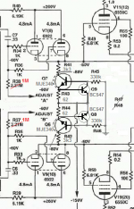
Adjusting the bias pots changes the grid voltage on V7 and V9 in you're diagram. At the cathodes of V7 and V9 you should be sitting somewhere around -50V +/- maybe 10 volts. This can be checked at pin 5 of the output tubes. Adjusting the bias pot should be changing the voltage up and down from -50 on pin 5 of the output tubes. Leave the output tubes out of it while checking but you'll need to leave the 6922s in (don't run the amp without the signal tubes). If it won't adjust right then check the other voltages around those two driver tubes and that quad of mosfets. If those fets go open or the -150 volt supply is missing you won't be able to get the bias supply down. When I blow them up they usually end up open. If they short the supply will be more negative.
Also doublecheck the condition of V7/V9. It's that tube and the mosfets that set the bias voltage. If they're weak then the bias voltage will be even more negative and it may not come up enough.
Don't put the output tubes back in until you get the right bias voltage at pin 5 of the output tube sockets and it adjusts with the pots. If the bias circuit works then it may be something else. When you think you got it set the bias even lower that -50 (like -60) and install the output tubes. Then use the regular bias procedure to bring them up. Watch them as it warms up. If it starts to run away shut it off.
I hope this makes some sense. And good luck.
Last edited:
One of the mosfet's in question is reading -150v on all pins.I just got an order in to replace.Also checked other voltages around amp and 6922's.At the 320v rail going to the 6.19k resistor-I should be getting 260v out but its 202 instead going to pin 6 and 1 of 6922's(V9 and V10).I changed the 6.19k resistor but no change.Also not getting 165v at C6(.33mf cap).I am getting -60 on the output of C6.
A new set of 6922's installed on side in question.
A new set of 6922's installed on side in question.
Last edited:
Just a spurious comment, but … gee… that sure is a beautiful balanced-through-the-entire-signal-path amplifier. Really sweet.
________________________________________
I personally only use MOSFET devices when they're the only outstanding part to do the job. And there definitely are outstanding applications for them. Yes… even as quixotic constant-current sources, they can be outstanding.
Problem is, as Mona / Ketje indirectly points out, the individual device-to-device manufacturing variation can be (and usually is) substantial. Its one thing to test a few hundred devices yourself over a few beers and a big pad of graph paper, to 'bin' them into very close matching quads; but … it is quite another thing to expect any given device that you purchase “today” to be even a remote substitute for one that is already in-circuit (and lets say, “blown”).
Moreover, again as Mona / Ketje indirectly points out, the drift-of-device-characteristic over both temperature ramps and time (i.e. life of amplifier) can be significant. If a MOSFET is run anywhere near its thermal limit, its channel doping ions can migrate … over years of operation … substantially. This in turn changes the ON and IDS0 points a fair amount (many percent).
Hence why the advice was good: bipolar don't drift anywhere near as much, nor are they so variable when you order a bag of them.
________________________________________
Just saying,
GoatGuy ✓
________________________________________
I personally only use MOSFET devices when they're the only outstanding part to do the job. And there definitely are outstanding applications for them. Yes… even as quixotic constant-current sources, they can be outstanding.
Problem is, as Mona / Ketje indirectly points out, the individual device-to-device manufacturing variation can be (and usually is) substantial. Its one thing to test a few hundred devices yourself over a few beers and a big pad of graph paper, to 'bin' them into very close matching quads; but … it is quite another thing to expect any given device that you purchase “today” to be even a remote substitute for one that is already in-circuit (and lets say, “blown”).
Moreover, again as Mona / Ketje indirectly points out, the drift-of-device-characteristic over both temperature ramps and time (i.e. life of amplifier) can be significant. If a MOSFET is run anywhere near its thermal limit, its channel doping ions can migrate … over years of operation … substantially. This in turn changes the ON and IDS0 points a fair amount (many percent).
Hence why the advice was good: bipolar don't drift anywhere near as much, nor are they so variable when you order a bag of them.
________________________________________
Just saying,
GoatGuy ✓
If all around the FET it's -150 then I'm guessing that's making the driver tube draw too much current and dragging its plate voltage down because now the driver cathode voltage is too low. Normally the driver cathode is -50 and the driver grid is -60. Now the cathode voltage is probably below the grid voltage and so it's loading down the supply.
If there is a problem with the coupling caps that would screw the whole thing up because you wouldn't be able to set the bias with the adjustment pots correctly. If the grid voltage at V7/8/9/10 is good then you're probably ok.
If there is a problem with the coupling caps that would screw the whole thing up because you wouldn't be able to set the bias with the adjustment pots correctly. If the grid voltage at V7/8/9/10 is good then you're probably ok.
If all around the FET it's -150 then I'm guessing that's making the driver tube draw too much current and dragging its plate voltage down because now the driver cathode voltage is too low. Normally the driver cathode is -50 and the driver grid is -60. Now the cathode voltage is probably below the grid voltage and so it's loading down the supply.
If there is a problem with the coupling caps that would screw the whole thing up because you wouldn't be able to set the bias with the adjustment pots correctly. If the grid voltage at V7/8/9/10 is good then you're probably ok.
That's the kind of info I've been looking for.Parts should be in tomorrow.I will surely let you know how it goes.
I put in the DN2530 you recommended and the voltage now around the mosfet output is -100vdc.( not the -80 vdc I was looking for).Also at the plates of V10 and V9-the voltage should be +260vdc after the 6.19k resistor coming off B+320 vdc PS.(which has gotten hot and turned brown)I'm measuring anywhere from 160 to 200 vdc.I don't know why.I get the 165vdc on front side of .33mf cap and the -60vdc on the other side.Still too unsure on putting in 6550's to blow up again.All resistors check out as marked on schematic.I'll also check my pcb traces to make sure solder isn't laying across and traces.
When you use the bias adjustment does it change the voltage at the cathodes of V7/V9? The goal was to get that around -50 +/- (with room for adjustment) which means that you would now have control of the grid bias on the output tubes.
The FETs from ARC are probably picked for specific Id and Vgs which is what the color coding is probably all about so the match may not be perfect. Swap V7 and V9 (or 10 or whatever) and see if it makes a difference. The low plate voltage is a little disconcerting but maybe the bias adjustment or tube roll will make a difference.
On the driver tubes the grid voltage should be lower than the cathode voltage. The exact value depends on the tube (the schematic shows 10v). If the driver draws too much current it lowers the driver plate voltage and raises the driver cathode voltage.
Good luck. Don't put the output tubes back in until you're confident you can control the grid voltage on each of the output tubes (pin 5).
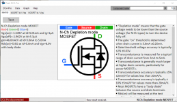
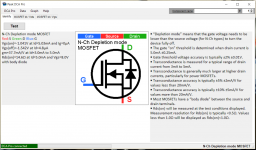
I used this thing to characterize the devices-
Peak Atlas DCA Pro model DCA75 | Peak Electronic Design Limited
Once I had the device parameters I started hunting down candidates. I'm sure you could do it with a power supply, a couple of resistors and a volt meter but you have to know what you're starting with. With this little guy you don't even have to know what the leads are, it tells you.
So you pull an original one, test it with the DCA 75 and then find a match. It's not the same as matching it like the factory does but it's a start.
Attachments
Mosfet Peak Measurements
I got the mosfets measured.Now which parameters do I need to be looking for?
Some of the data at Mouser doesn't match too well.I checked the diodes I got from Mouser you recommended and they were shorted out.New measure fine-of course.
I got the mosfets measured.Now which parameters do I need to be looking for?
Some of the data at Mouser doesn't match too well.I checked the diodes I got from Mouser you recommended and they were shorted out.New measure fine-of course.
Attachments
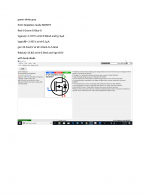
I looked at Vgs on and Vgs off. If the 2530 is too low the 2535 was higher (well more negative). They spec them by range. I bought more than I needed and picked the best match. The Id values given by the tester are fixed parameters for the test, like 5ma. For parallel devices Rds might be useful.
- Home
- Amplifiers
- Tubes / Valves
- Mosfet for Bias control in ARC VT200