Hi there I have a pair of leak TL12+ amps that need fair bit of work to bring them back to good order. One works but has had a lot of work down to it over the years and is in need of a good tidy up along with some better quality parts in a number of locations, the other was reported to have had an flashover in the rectifier and C11(grid leak capacitor 47uf) has blown itself to bits. My questions concern some of the component values which differ from either the Values in the little Leak amp pamphlet (the one with 100/60 as the main caps) and also component changes as recommended in the Morgan Jones valve amp book when changing an EF86 to triode operation which is what has been don here.
First the main filter capacitors. A previous restorer has put 8 and 20 uf where the 60-100 should be and 45+45 where the 8 and 16 should be. my plan is to put a 50+50 inside the main capacitor can after I have hollowed it out to keep the look and then 10+22 for the other capacitors. Any thoughts on this, the amp will be used with a modern tube Pre amp so the pre amp power supply will not be used ,would I be better off using 32+32 as the main filter to reduce the stress on the GZ34?
My other concern is about the feedback components and the phase correction components across the EF86 anode load. The phase correction capacitor resistor across the anode load has been changed, the resistor shown as R23 on leak's diagram has been removed and the capacitor value reduced from 300pf down to 100pf and wired straight across the anode load. The feedback loop components are also different, the main resistor is now 27k rather than 12 and the capacitor has been change to 100pf.
My experience of electronics is predominantly with Semiconductors and digital so I don't know whether these changes have been done for a good reason or whether they are in error, the error with the main capacitors has me concerned that they could be in error. I do have access to a good oscilloscope and signal generator so could rebuild it with the current values and is and then test for ringing and oscillation but if someone could give me some advice as to what to do I would be most grateful.
As no one else has responded, I'll kick it off.
First make sure you have a pair. Look at the number on the output transformers. It will be either 3921 (early) or 8778 (later).
There are two types of mains transformer to match the output types. The earlier one has a higher voltage HT (B+) so measure the AC volts on pins 4 and 6 of the GZ34. 300v ac vs 280v ac. It is not unusual to have 'combinations' after this time from manufacture.
So some component values changed too. Most important is to have 470k resistors for the EL84 grid leaks R16 and R17. They started at 1M ohm, but that caused thermal run away in the output pair. I cannot remember now, but R5, R23 and C15 values may have altered over time, but 82k, 4.7k and 200pF are 'normal'.
I would go back to the original design values there and in the feedback loop and get them functional.
The big can cap was originally 60 + 200uF by the way. Not sure the GZ34 is under any real stress unless the coupling caps C8 and C10 are leaking... But you could use 47 or 50uF for the first one and not notice any real difference in noise/ripple. Unfortunately modern GZ34s can be a bit less than reliable. And some are not even genuine GZ34s but re-badged...
enough now, Alan
For info, C11 and C12 are 'cathode bypass caps'.
HI Alan, thanks for being the first to reply. Both my amps have 3920 power transformers although one is a 3920R. The other difference is that one has a round mains input plug and a terminal strip for the loudspeaker connections. The one that has the 3920R has a tag block as the mains input which looks like it was really made to be built inside something. It has 470k resistors for the grid leaks so thats good, and I am changing C8 and C10 for selected russian paper in oil capacitors so that avoids issues with their leaking.
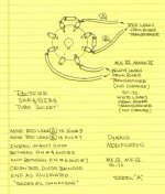
The SS series diode tweak makes the affordable Sovtek 5AR4 (GZ34) an excellent option. The New Sensor product is fully capable of delivering the rated 250 mA. The Saratov, Russia, product can demonstrate a weakness at the top end of the documented voltage range. The SS diodes in series with the plates add some PIV headroom and completely dispose of the matter.
FWIW, I prefer UF4007s over the 1N4007s shown. In spite of vacuum diodes blocking SS diode switching noise, my thinking is that less noise, from the outset, can't hurt and may help. UF4007s cost 41 cents in the U.S. and should be correspondingly low cost in the U.K.
FWIW, I prefer UF4007s over the 1N4007s shown. In spite of vacuum diodes blocking SS diode switching noise, my thinking is that less noise, from the outset, can't hurt and may help. UF4007s cost 41 cents in the U.S. and should be correspondingly low cost in the U.K.
Attachments
- Status
- This old topic is closed. If you want to reopen this topic, contact a moderator using the "Report Post" button.