tl;dr thread until now- I was planning to build a 45 based amp for headphones and was unsure which OPT to buy (to optimize for 64-300 headphones), and whether load resistors are required. ----
Fast forward few months, I ended up buying 5K:32 OPT's and my build is now almost complete. I made a few measurements in ARTA. (I'm new to using this system so please correct me if I did anything wrong).
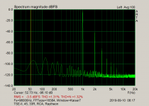
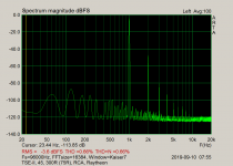
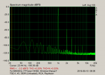
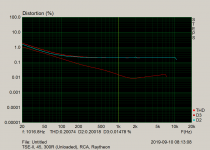
I measured the with 33R, 300R (no load resistor) and 300R (w/ 75R load resistor, effective load 60R). ARTA generated a -3dbFS signal and I set the volume to match as close as possible.
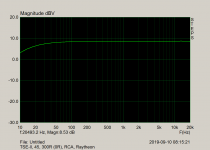
Distortion was best on the 300R load, followed by 60R and then 33R. FR was pretty similar, maybe slightly more lower end roll-off on the unloaded 300R.
I am surprised that the 300R load performed better without any load resistors.
Fast forward few months, I ended up buying 5K:32 OPT's and my build is now almost complete. I made a few measurements in ARTA. (I'm new to using this system so please correct me if I did anything wrong).
I measured the with 33R, 300R (no load resistor) and 300R (w/ 75R load resistor, effective load 60R). ARTA generated a -3dbFS signal and I set the volume to match as close as possible.
Distortion was best on the 300R load, followed by 60R and then 33R. FR was pretty similar, maybe slightly more lower end roll-off on the unloaded 300R.
I am surprised that the 300R load performed better without any load resistors.
Attachments
....I am surprised that the 300R load performed better without any load resistors.
Simple amplifiers make lowest distortion with "least load". 32r is heavy load, 300r is light load, for a "32r" tap.
The flip side is that a 300r load would typically need more *voltage* to get the same loudness. For equal-power, the 300r should be driven 3X the Voltage (+10dB) of a 32r. However I have observed that the hi-Z phones tend to be more sensitive, the 32r phones are often indifferent about efficiency, so maybe not a big deal. Especially since you seem to have 10X the power any phone needs to blow your brains out your nose.
Hi Guys,
I have a similar query regarding the output on a VTA m125 -parallel push pull with kt88s.
The amp is designed for 4x kt88 but it turns out I don't need remotely that level of power so I have only ever ran these with a pair of kt88s in each.
The OPT is an 8k and I am using the 4ohm taps to power some dynaudio audience 42 speakers (nominal 4 ohm).
If I am correct in my thinking. What I am looking at here is the inverse of the itsikhefez was dealing with.
My thinking is as follows: if the amp were using 4x kt88 per channel, that 8k OPT is being shared by the 2 kt88s on either side of the pushpull. Therefore, by only running 1 kt88 per side of the push pull, each kt88 is dealing with a higher resistance load.
I don't yet have any equipment for measuring such things. But assuming my thinking is correct: as currently used with a single pair of kt88s per channel, the amps are likely putting out slightly less power but at a lower distortion due to driving an easier load?
People get confused by THD graphs for power pentodes that show increase of distortions with increase of load resistance after the tube starts saturating, such ^ - shaped curves. You should interpret that curves properly. If to keep the anode voltage swing below saturation distortions with increase of load resistance decrease, and only decrease.
> each kt88 is dealing with a higher resistance load.
What Wavebourn said. The tube-charts are drawn for *constant* grid drive and often extend into clipping.
In real life, if it distorts, you Turn It Down.
For any tube amp: the lowest THD is at infinite load. However this is also zero power output. So we use the highest load which gives the required power without getting into clipping. But commercially, if you paid for two 6L6, you must extract "ALL" the 40 Watts you have paid for, so you lower the load accordingly.
Your quad 6550 amp would *probably* show lower test THD with all four tube working. It doubles the load impedance on each tube, working more constant-current. However if you are so far from quad-6550 levels that you could consider removing a pair, it probably don't matter a bit.
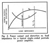
For push pull the distortion line will flatten out but this is grossly the idea. You are shifting the load to the Rl=rp point:
It is a no-feedback curve, misleading. Internal resistance of the pentode is huge, so on such load resistances voltage swing would be proportional to the load resistance, so the power grows up, then the tube starts saturating.
")
Avoid saturation, and "D" curve will go down and only down, and power curve will go down sharper after the peak than drawn.
You are not going to run your pentode amp without feedback past clipping, are not you?
Last edited:
Well... I keep the penthodes for next year, for now I have my hands full of all that heavy ironYou are not going to run your pentode amp without feedback past clipping, are you?
Got me a nice couple of KT66s so once I'll have a go with that anode to grid feedback
Simple amplifiers make lowest distortion with "least load". 32r is heavy load, 300r is light load, for a "32r" tap.
The flip side is that a 300r load would typically need more *voltage* to get the same loudness. For equal-power, the 300r should be driven 3X the Voltage (+10dB) of a 32r. However I have observed that the hi-Z phones tend to be more sensitive, the 32r phones are often indifferent about efficiency, so maybe not a big deal. Especially since you seem to have 10X the power any phone needs to blow your brains out your nose.
Thanks for the further information.
One follow up question here is, while I see that the lighter load is fine/better for the tube, can the same be said for the OPT?
I was under the impression it is designed to output the given frequency range with a specific load on the secondary.
My initial FR tests in ARTA show that there isn't much if any roll-off with the "mismatched" load, but was curios what the theory is here.
Losses in the frequency domain come from unintended inductive and capacitive coupling and from wire resistance. Also the allowence for DC and the elektromagnetical properties of the core material play a role.
For instance, if you had asked for two secundaries (32R and 300R) the OP would have had more copper wire, if not accounted for by the winding scheme that would lead to more parasitic capacitance between layers and more parasitic inductance. It's a balancing act to arrive at optimal results.
For instance, if you had asked for two secundaries (32R and 300R) the OP would have had more copper wire, if not accounted for by the winding scheme that would lead to more parasitic capacitance between layers and more parasitic inductance. It's a balancing act to arrive at optimal results.
A transformer needs either its input or output to be a "low" impedance.
In triode amps the triode is a low impedance, and typically dominates the load impedance. Remeber that we load triodes with 2X to 5X the Plate resistance. Taking the load to infinity makes very little difference on what impedance the transformer "sees".
In triode amps the triode is a low impedance, and typically dominates the load impedance. Remeber that we load triodes with 2X to 5X the Plate resistance. Taking the load to infinity makes very little difference on what impedance the transformer "sees".
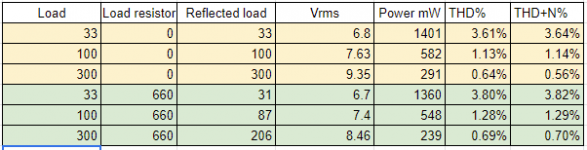
To wrap up this thread and in case this helps anyone build triode amps for headphones in the future- I ran measurements in ARTA with loads of 30, 100 and 300 ohms (representing possible headphones), with load resistors ranging between 0 and 660ohm.
I attached a table with max power before clipping (maybe slightly before that)
with the 5K:32R OPT.
The amp put out the most power with least distortion without load resistors at all.
I ended up ordering 750ohm/2W resistors as load resistors, for safety in-case headphones are unplugged while loud music is playing.
If I'm not mistaken, there should be less than ~100mW on the output in that case.
Attachments
- Status
- This old topic is closed. If you want to reopen this topic, contact a moderator using the "Report Post" button.
- Home
- Amplifiers
- Tubes / Valves
- Understanding load on triode and impedance matching