Hi,
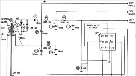
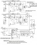
I'm having trouble at power up of a tube stereo that I rebuilt from the chassis/transformers up. It's an early '60's Silvertone out of a console. I pretty much rebuilt it to the stock schematic (attached). The only exceptions are increased filter capacitance (220ufs in place of the 120 and 100 and 68ufs in place of the 40s), a 470k bleeder resistor across the first filter cap, and a diode powered by an unused 7-volt winding that originally powered a different part of the console. This is across the now unused original speaker terminals and isolated from the rest of the circuit.
The symptom was an exceptionally loud rattling of both OT's with zero signal applied as I crept up towards 70VAC on the variac.. I measured it a 17HZ (I believe it was about 4 volts at full 120vac) and put a little cheapo speaker across each just to hear what was a low crackle/sputter (motorboting?).
As the circuit has negative feedback, my first test was to disconnect it an that allowed the amp to be brought up to full voltage without mechanical noise from the OT and maybe 5mv ac on the secondary. I then flipped the OT secondaries. However, doing this brought about the theremin sound from the OTs (no speaker) that is more classic of the positive feedback associated with that mistake so I put the secondaries back.
I also checked for AC ripple on the power supply and found that at the full 120vac, it was jumping around 3 volts ac (120hz) at the first filter cap. This seemed high to me (though I haven't dealt with a voltage doubler circuit before) so I then started looking at the power supply/caps, as well as swapping tubes. I variac'd up with everything from no tubes to a single complete channel (rotating all four of the power tubes and both preamp tubes in and out), to power tubes only for a single channel, to preamp/pi tube only for a single channel (both channels tested). All of this and the info below is taken with negative feedback disconnected and thermistor bypassed.
I also alligatored an additional 47uf/400v cap across each of the 4 power supply caps (but did not desloder them, is that necessary to properly test) in the circuit and this produced no change.
In all cases, I found that that at around 50-60v ac, the ripple on the first cap would start to shoot up and often keep jumping around. Below are some measurements:
No tubes/120vac/350vdc: Ripple mainly jumps from 20-50mv, but occasionally spikes to 75mv and once or twice hits 100+.
1 preamp/pi tube installed/120vac/348vdc: Ripple jumps from 50-100mv.
2 power tubes (i.e. one channel)/65vac in/171vdc: Fairly stable 650 mv of ripple. Goes up to 1 volt.
So, is the power supply ripple a problem and the likely culprit for the transformer noise/voltage present when the negative feedback is attached.
If not, do any other causes for problems come to mind, or is anything visible from the pics?
I also was not completely content with the loose fit of some of the power tubes into the sockets, and my have put excessive soldering iron heat on one of the diodes.
Are there particular steps I can take to isolate sections of the circuit for troubleshooting? I actually have a homebrew tube tester whose full-wave power supply/heater supply could power one channel.
Thanks as always!
Joe
Attachments
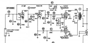
In your rebuild did you ensure that the grid stoppers R69, R71 were right on the output grid tags? HF oscillation can sometimes present itself as LF oscillation.
You could try varying the values of C79 and C80, up or down. It is important that the LF rolloff they give is well separated in frequency from the OPT LF rolloff.
You could try varying the values of C79 and C80, up or down. It is important that the LF rolloff they give is well separated in frequency from the OPT LF rolloff.
The output stage does not require a really smooth supply as it is balanced. 3volts ripple is better than most.
17HZ is a weird frequency but I surmise you fixed that by disconnecting the NFB loop. (Just as an aside, 17HZ is flicker frequency of a candle).
The original Silvertone has approximately 8volts ripple on the Source supply and when under load about 25volts of supply sag. As long as the 265volt supply is smooth, it should be quiet.
I did not do that with the resistors, but will. Also, great to know that the ripple here is not abnormal.
If I was just running this at low power (1-3 watts/90+ db speakers) in my apartment, would leaving the negative feedback off altogether significantly change the audio characteristics? I'm assuming that the cap in the circuit is targeting some frequencies...
Thanks!!
Joe
If I was just running this at low power (1-3 watts/90+ db speakers) in my apartment, would leaving the negative feedback off altogether significantly change the audio characteristics? I'm assuming that the cap in the circuit is targeting some frequencies...
Thanks!!
Joe
So I've been troubleshooting this on and off, incorporating the ideas offered and while I'm not out of the woods, I may have made a useful discovery. With the right tube combo, 1 of the channels seems stable even with the negative feedback connected. I had been probing at 2/3-3/4 voltage on the variac but I now realize that if I just let the circuit come up at full voltage, it will work eventually. However, there is a period of 10 or so seconds with about 6 volts on the OT secondaries before the circuit stabilizes and there is maybe 10-15mv there. At that point, I can connect a cheapo speaker across it and it's pretty quiet. That drop is pretty abrupt when it happens.
Any ideas?
Thanks again!
Joe
Any ideas?
Thanks again!
Joe
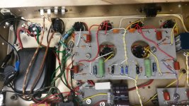
there is something that asks me about heating wiring your ax7.
I see that 4 and 5 are wired with two wires and that 9 has a single wire that serves as common.
a month that you wanted the cable in 12v, this is not the right way for 6.3 v.
you must have your two sons on 4 and 9 and make a bridge between 4 and 5.
afterwards, I may be wrong, but as I have already had while working in a nest of rats, I prefer to say it.
Thanks. It looks that way in the picture but the double wiring is actually going to 5 and there is a bare wire jumper between it and 4. The 2 wires are one coming from the previous tube and one going to the next. BTW, I'm starting to think that may problems could be due to bad tube sockets so I'm going to change all those out.
Joe
Joe
Thanks to all who weighed in. I think I found the problem: me. I was so segmented in my testing that I never brought it up with both channels connected to speakers/loads on the OT secondaries (btw, I never applied a signal as part of the test, so didn't think I needed to). Once I did this, it came up no problem several times in a row, with no temporary voltage spikes and no more than a few millivolts ac on the secondaries at idle, and all of this with negative feedback attached.
If anyone could confirm that this makes sense and, all other things considered, I should have a stable amp, I'd appreciate it.
Thanks again!
Joe
If anyone could confirm that this makes sense and, all other things considered, I should have a stable amp, I'd appreciate it.
Thanks again!
Joe
You mean you powered up one channel without a load? Not a good idea, it can burn out your OPT.
Just a note,I've had problems with those small brown Vishay resistors your using going high causing Vk to go very high, might be worth keeping an eye on them if they're in an application where they can get hot.
Andy.
Just a note,I've had problems with those small brown Vishay resistors your using going high causing Vk to go very high, might be worth keeping an eye on them if they're in an application where they can get hot.
Andy.
Hmmm. Those beefier bypass caps seem a potentially sweet prospect. Right now I still need to do some final clean-up, put signals through it, add new speaker jacks, and get music running through it. Once that happens and I know I like it, I'll likely follow your advice. I do like to make sure these sorts of build work first in their original condition before the mods but this one does run exceptionally hot even at idle so cooling it off a bit so long as it does not adversely affect sound will be a good thing.
Thanks for the tip!
Joe
Thanks for the tip!
Joe
I don't know why the original used 100 ohm cathode resistors - because those output tubes always ran with 130 to 150 (cooler) resistors, which I use and suggest.
An excellent ultralinear amp that I built years ago has outstanding performance, using a novel regulated biasing system, yet it's simple. The amp's got punch, drives inefficient speakers well, and gives 17 watts/per. Of course, I used the "new issue" Dynaco Z575 output transformers for this. Triode Electronics online sells them as replacements and new designs.
An excellent ultralinear amp that I built years ago has outstanding performance, using a novel regulated biasing system, yet it's simple. The amp's got punch, drives inefficient speakers well, and gives 17 watts/per. Of course, I used the "new issue" Dynaco Z575 output transformers for this. Triode Electronics online sells them as replacements and new designs.
Attachments
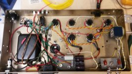
Almost there! I had some orphaned eyelets on my main board that were perfectly positioned to just add 2-watt, 47ohm resistors in series with the hundred ohm resistors that were there already. I also added 47uf 65v bypass caps that were on hand at my MakerSpace. Signals look good on the scope, and are giving me about 10 watts of clean power. The only thing is that my voltage at the first filter cap is around 320 volts as opposed to the 310 specified. Is it worth my time to bring that down?
Thanks as always!
Joe
Thanks as always!
Joe
- Status
- This old topic is closed. If you want to reopen this topic, contact a moderator using the "Report Post" button.
- Home
- Amplifiers
- Tubes / Valves
- LFO/Ripple in Tube Stereo Rebuild on First Power-Up