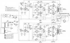
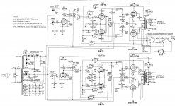
I have a Citation II amplifier that I have completely rebuilt using McShane kits. Besides the transformers, choke, bias meter and selector switch, everything electronic is new. A schematic showing the amp as-built is attached.
The amp hums, and I cannot figure out why. The facts:
I feel like the fact that the 120Hz hum/buzz is 180 degrees out of phase between the two channels and can be eliminated by shorting either input should be a HUGE clue, but I am drawing a blank.
Where should I look? Why is the hum inverted? Why does it go away when I short either input?
------EDIT-------
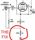
The amp was suffering from a cross-channel ground loop that was created whenever anything was attached to the amp. The above described issue is a classic sign of this kind of loop. I fixed the issue by installing a hum break resistor (HBR) at the ground of the input sections. Schematic and description here.
The hum is entirely eliminated. Noise is 0.1mV RMS or less at the outputs.
The amp hums, and I cannot figure out why. The facts:
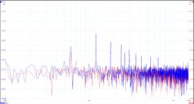
- The hum is 120Hz with lots of harmonics (spectrum attached)
- The hum is about 1.4 mV RMS
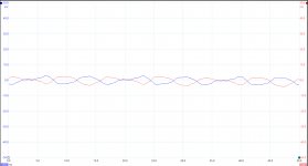
- The hum is 180 degrees out of phase between the two channels (scope reading attached)
- I can completely eliminate the hum if I short the input of Channel A, the input of Channel B, or both. I do NOT need to short both channels to eliminate the hum.
I feel like the fact that the 120Hz hum/buzz is 180 degrees out of phase between the two channels and can be eliminated by shorting either input should be a HUGE clue, but I am drawing a blank.
Where should I look? Why is the hum inverted? Why does it go away when I short either input?
------EDIT-------
The amp was suffering from a cross-channel ground loop that was created whenever anything was attached to the amp. The above described issue is a classic sign of this kind of loop. I fixed the issue by installing a hum break resistor (HBR) at the ground of the input sections. Schematic and description here.
The hum is entirely eliminated. Noise is 0.1mV RMS or less at the outputs.
Attachments
Last edited:
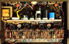
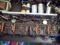
It's nearly 4 AM here, and my lighting is terrible, so the photo is not ideal. Sorry about that. But between it and my description below, I think you should be able to make sense of it.
The filament grounds are attached directly to the chassis. Channel A's filament grounds is attached to one of V9's tube socket screws (center left socket). Channel B's filament ground is attached to one of V8's tube socket screws (center right socket). This was the recommendation of Jim McShane.
The ground for the bias meter attaches directly to the chassis using the screw that holds the meter to the chassis.
The test signal jack resistor grounds directly to the chassis using the screw immediately to its left. The input line shields ground to the chassis directly next to their respective jacks. The jacks themselves are isolated from the chassis. All the other grounds attach to the PSU bus bar.
The PSU components attach to the bus bar in this order, from left to right: Rectifiers --> Reservoir Caps -->Filter Caps (stacked) -->Decoupling Caps --> Bias Supply. The bus bar grounds to the chassis midway between the rectifiers and the reservoir caps (Jim McShane's recommendation). That is the only point at which the bus bar grounds to the chassis. On the bus bar, I chose the point midway between the two decoupling caps as a "central star point" at which all the remaining grounds would ultimately meet.
The grounding scheme for each channel is the same. Using Channel B (the channel on the right in the photo) as the example, and following along the terminal board from left to right:
Pin 4 of the terminal board is the ground at R12. A wire runs straight from the end of that resistor to the bus bar star point.
Pin 9 of the board is a "secondary star point" where the following grounds meet: the input jack ground, R2, R3, and the OPT ground. From there, a single wire runs to the bus bar star point.
Pin 13 of the board is another "secondary star point" consisting of R16 and the un-named bypass cap seen above R5. From there, a single wire runs to the bus bar star point.
R29 is grounded to the bus bar star point via a short wire.
R30 is grounded to the bus bar star point via a short wire.
R26 is located at the back of the amp, and grounds to the bus bar star point by its own wire.
Channel A's grounds are arranged the exact same way, but since it is so far from the bus bar star point, all its ground lines meet at the one point you see in the photo, and from there a single line runs to the bus bar star point.
Oh yes! With nothing attached the amp rages. The hum I am describing occurs with any and all of my preamps and other devices attached.
I should say, Jim McShane recommended grounding all the "DC Grounds" using the shortest path to the bus bar. I followed that recommendation and got a lot of hum.
I then looked at the photo he sent showing his ground scheme, and noticed he grounded everything for Channel A at the decoupling cap ground, and everything for Channel B at the point midway between the reservoir caps and the rectifiers -- one "star point" for each channel at two points on the bus bar. I did that, and the noise was less, though still quite prevalent.
The scheme I described above has, so far, been the quietest.
All that said, I feel like there is something else afoot, as Jim McShane and many others have found success using all the schemes I described above.
The filament grounds are attached directly to the chassis. Channel A's filament grounds is attached to one of V9's tube socket screws (center left socket). Channel B's filament ground is attached to one of V8's tube socket screws (center right socket). This was the recommendation of Jim McShane.
The ground for the bias meter attaches directly to the chassis using the screw that holds the meter to the chassis.
The test signal jack resistor grounds directly to the chassis using the screw immediately to its left. The input line shields ground to the chassis directly next to their respective jacks. The jacks themselves are isolated from the chassis. All the other grounds attach to the PSU bus bar.
The PSU components attach to the bus bar in this order, from left to right: Rectifiers --> Reservoir Caps -->Filter Caps (stacked) -->Decoupling Caps --> Bias Supply. The bus bar grounds to the chassis midway between the rectifiers and the reservoir caps (Jim McShane's recommendation). That is the only point at which the bus bar grounds to the chassis. On the bus bar, I chose the point midway between the two decoupling caps as a "central star point" at which all the remaining grounds would ultimately meet.
The grounding scheme for each channel is the same. Using Channel B (the channel on the right in the photo) as the example, and following along the terminal board from left to right:
Pin 4 of the terminal board is the ground at R12. A wire runs straight from the end of that resistor to the bus bar star point.
Pin 9 of the board is a "secondary star point" where the following grounds meet: the input jack ground, R2, R3, and the OPT ground. From there, a single wire runs to the bus bar star point.
Pin 13 of the board is another "secondary star point" consisting of R16 and the un-named bypass cap seen above R5. From there, a single wire runs to the bus bar star point.
R29 is grounded to the bus bar star point via a short wire.
R30 is grounded to the bus bar star point via a short wire.
R26 is located at the back of the amp, and grounds to the bus bar star point by its own wire.
Channel A's grounds are arranged the exact same way, but since it is so far from the bus bar star point, all its ground lines meet at the one point you see in the photo, and from there a single line runs to the bus bar star point.
Have you tried connecting some source device to it?
If left open, it hums for sure with 1Meg at the input.
Oh yes! With nothing attached the amp rages. The hum I am describing occurs with any and all of my preamps and other devices attached.
I should say, Jim McShane recommended grounding all the "DC Grounds" using the shortest path to the bus bar. I followed that recommendation and got a lot of hum.
I then looked at the photo he sent showing his ground scheme, and noticed he grounded everything for Channel A at the decoupling cap ground, and everything for Channel B at the point midway between the reservoir caps and the rectifiers -- one "star point" for each channel at two points on the bus bar. I did that, and the noise was less, though still quite prevalent.
The scheme I described above has, so far, been the quietest.
All that said, I feel like there is something else afoot, as Jim McShane and many others have found success using all the schemes I described above.
Attachments
One thing I fount when building a pre-amp. Was too double check the isolation on the RCAs. I found that on one occasion I had not cleaned out the RCA holes properly. I verified isolation and it was good. I then aligned and tightened them.
When I finished the pre there was hum. I chased my tail for a couple of days. I started pulling star earths, and found the rca ground was shorted too ground.
I have learnt to also make my Star earth points easy to disconnect, that way you can verify isolation from ground.
Good luck with your hum hunting
“The input line shields ground to the chassis directly next to their respective jacks. The jacks themselves are isolated from the chassis. “
Looking at this bit.
Is the shield grounded at both ends of the cable?
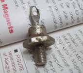
When I rebuilt my Cit II several years ago I did not attach the input cable or jack to the chassis but ran the input and the shield from the jack through the shielded cable with the input connecting to the turret board at post #27 and the shield connected to post #28 only. This eliminates any ground loop between the chassis and post #28 which is the ground for the input tube. A picture of my CitII before rebuild. Note the rectifier diodes for the B+. They were 50V 20A Shottkey diodes, I was amazed that they were not shorted! Close up of diode removed from Cit II 1N3899 http://www.digitroncorp.com/Documents/Datasheets/1N3899-1N3903.aspx?ext=.pdf
Attachments
No, just the one endIs the shield grounded at both ends of the cable?
The cable I'm using has three conductors: two for signal, one for the shield. The shield line is attached to the chassis. The signal conductors are attached to the jack and then to the input turrets (27 & 28).When I rebuilt my Cit II several years ago I did not attach the input cable or jack to the chassis but ran the input and the shield from the jack through the shielded cable with the input connecting to the turret board at post #27 and the shield connected to post #28 only. This eliminates any ground loop between the chassis and post #28 which is the ground for the input tube.
Anyone with a Citation II willing to measure the noise at their outputs? Ground to 16 ohm tap? A simple multimeter reading in mV will do. I'm curious as to how far off this is.
===
I figured out the problem.
My amp suffers from a cross channel (inter-channel) ground loop. The solution is a "hum breaking resistor" My question is, where should I put it? I see some people advocating I put it in series with the 0v line running from my RCA Jack's ground. Is that correct?
These are not the B+ rectifiers but the two diodes to the right of the choke; they are never reverse biased, they only carry dc current. The actual rectifiers which do get reverse biased with B+ are SR1... SR4 in a voltage doubler configuration.A picture of my CitII before rebuild. Note the rectifier diodes for the B+. They were 50V 20A Shottkey diodes, I was amazed that they were not shorted!
As a side issue, i don't know why you would want to use an amp like the 'deuce' to power any sensitive or high efficiency type speakers. It is really designed for the opposite type like difficult to drive multi speaker systems of moderate to low efficiency. Just my opinion. Anyway, I own 2 of them and frankly i don't enjoy them as much as my other amps.
Does the amplifier's two channels supply power independently or share a group of power supplies?My English is very poor
The supply uses one transformer, but it is split after the choke. See the schematic, attached to my first post


The Fix
I fixed the problem by adding a 10 ohm "hum break resistor" at the end of each of the Citation II's input section grounds between them and the bus bar. I attached a schematic to show you what I mean.
I implemented the fix using Pin 40 on the turret boards as local star points for each input section. I snipped the jumper from Pin 40 to Pin 9, and in its place mounted the 10ohm resistor.
Since I wanted to make sure the global NFB loop was referenced properly, I ran the ground and feedback wires for the OPTs back to their respective turret boards in twisted pairs, connecting the feedback wires to Pin 8, as usual, but the OPT grounds to Pin 40 (the local star).
Attachments
- Status
- This old topic is closed. If you want to reopen this topic, contact a moderator using the "Report Post" button.
- Home
- Amplifiers
- Tubes / Valves
- Citation II Hum! Lots of clues, but I'm clueless...