Hi
Just two months ago on Audioreview magazine oin Italy I wrote an article about the tube crossover, 12 dB /octave
In attach the schematic.
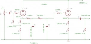
Fig. 1 is the low pass
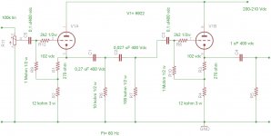
Fig. 2 il the high pass
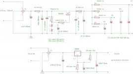
Fig. 3 is the power supply
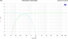
Risp is the freq. response of the two filter, tuned at 350 Hz.
The filter is 12 dB octave, to set at 6 dB, you just remove the second R-C Filter.
To set the value of R and C the formula is simply.
I fix the R at 10 kohm so :
F= 1 / 6.28 x C x R
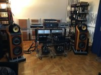
The project was tuned for a pair of B&W 800D driven by four monos made by me with KT150 each one, 290 watt dynamic power.
The frequency cut was tuned related to the internal crossover of 800D.
The attachment
Walter
Just two months ago on Audioreview magazine oin Italy I wrote an article about the tube crossover, 12 dB /octave
In attach the schematic.
Fig. 1 is the low pass
Fig. 2 il the high pass
Fig. 3 is the power supply
Risp is the freq. response of the two filter, tuned at 350 Hz.
The filter is 12 dB octave, to set at 6 dB, you just remove the second R-C Filter.
To set the value of R and C the formula is simply.
I fix the R at 10 kohm so :
F= 1 / 6.28 x C x R
The project was tuned for a pair of B&W 800D driven by four monos made by me with KT150 each one, 290 watt dynamic power.
The frequency cut was tuned related to the internal crossover of 800D.
The attachment
Walter
Attachments
Yours is looking different. One high pass and one low pass.
I need one high pass, and two band-pass filters with what I want to achieve, plus correction to compensate for high-frequency horn/driver combinations response dip.
Asking around I am also not recommended to use 6922 as they are too colored (a little on the bright side). Maybe I need a completely new design.
100hz-500hz
500hz-5khz
5khz-open (7.6khz 6db boost)
The 6922 is not colored at all. Its sound depends, as others, on bias point. I use 6 mA and -2 volt with 200-220 volt. If used as CF it works perfect. With the control of attenuation you can trim the level.
After that you can't set the frequency cut without the exact shape of freq. answer of louspeaker and his crossover. The risk is the phase change around the frequency of crossover. In my case I set the cut around 4-5 time of the original cross over frequency. So the phase change respect of original is less than 20°, and it be considered fine.
Walter
My recommendation is to dig through the Linkwitz site extensively- specifically this page-
Active Filters
Nearly all of these can be implemented with tubes, to varying degrees of complexity. The bandpass filter is a little tricky with tubes if you want it simple.
I know tubecad has his filter designer, but if I'm not mistaken it only does high/low, no badpass, stop, or shelving.
For the -3dB dip at 13khz you want a notch filter. Figure 7B and C can be accomplished with tubes by replacing the opamp and using a cathode follower.
May be useful-
https://scholarsmine.mst.edu/cgi/viewcontent.cgi?article=7686&context=masters_theses
You can always cascade high/low pass filters as needed but getting it right is more than trivial. You may end up overdamped and/or at the wrong "Q" but it also depends on how the drivers interact, you may wish to do some of it passive at the speaker and some at the line level for a mixed solution.
Last edited:
The 1st order XO is basically a buffered PLLXO. It frees you from worring about the input impedance of the amps that have a high pass filter in front of them.
Looking at Broskie's schema, since the filter is after the buffer it will still be affected by the input impedance of the amp. Waltube’s is better i would think. If you have a preamp with low enuff output impedance i expect you could nuke the 1st CF. ie a PLLXO with an output buffer — really only needed on the HP filters.
It is also noted that a cathode follower gets much better with a CCS on its tail.
dave
I'm a die-hard tube guy, and even I think this is a job for op-amps. A handful of OPA2132PA or LM4562 would be a great way to go here that will surpass most commercial offerings when done right. I feel so strongly about it that I invested considerable time into designing a PCB for it too ")
Or, go with the Pass LXmini jfet crossover boards and modify them to suit
Or, go with the Pass LXmini jfet crossover boards and modify them to suit
O(perational) Amp(lifiers) were invented EXACTLY for this kind of job and notyhing else, which they do admirably.
Their use in frequency shaping equalizers, crossovers, etc. , is the problem waiting to be solved with Op Amps.
That they also can amplify linearly is the icing of the cake, besides it being the simplest "operation" they can perform on Audio: linear and flat amplification "X" times.
Their use in frequency shaping equalizers, crossovers, etc. , is the problem waiting to be solved with Op Amps.
That they also can amplify linearly is the icing of the cake, besides it being the simplest "operation" they can perform on Audio: linear and flat amplification "X" times.
For a simple buffered line level crossover that doesn't need steep slopes or extensive waveform shaping tubes are fine, and work well enough. For advanced stuff like what OP wants I would use something else.
I've done a few simple high/low crossovers that were simple tube gain stages followed by cathode follower sandwiches containing cascaded filters, they work well, but can be a bit complex. For an application where you want to pair a flat fullr ange with a subwoofer or midwoofer they are a nice way to go.
I've done a few simple high/low crossovers that were simple tube gain stages followed by cathode follower sandwiches containing cascaded filters, they work well, but can be a bit complex. For an application where you want to pair a flat fullr ange with a subwoofer or midwoofer they are a nice way to go.
Last edited:
Last year I build a tube subwoofer filter which needed a high value output cap. It blew my class D amp beacuse of DC on the output while starting up. So I would recommend a timer with relay to shorten the output for like 20 secs.
The filter sounded perfect BTW better than opamps IMO. Of course it is 3 times as large.
The filter sounded perfect BTW better than opamps IMO. Of course it is 3 times as large.
To you Dave, you really should qualify your pontifications a little more.I would not use OpAmps. A CCSed JFET buffer makes more sense.
But the satisfaction to make a tube stuff is completely different for many reason.
My opinion
Opamps are convenient for weird textbook active filters, while I like very much Walter's approach, with buffered passive filters. Minimum of non-linear distortions and unwanted phase artifacts. I did the same utilizing input resistance of JFETs. Sounds gorgeous.
O(perational) Amp(lifiers) were invented EXACTLY for this kind of job and notyhing else, which they do admirably.
Their use in frequency shaping equalizers, crossovers, etc. , is the problem waiting to be solved with Op Amps.
That they also can amplify linearly is the icing of the cake, besides it being the simplest "operation" they can perform on Audio: linear and flat amplification "X" times.
Actually they were invented for applications such as artillary gun directors and analogue computers:
http://www.tayloredge.com/museum/museum/opamp.pdf
Getting back on topic, isn't 6 dB/octave a bit low for most drivers?
Last edited:
- Status
- This old topic is closed. If you want to reopen this topic, contact a moderator using the "Report Post" button.
- Home
- Amplifiers
- Tubes / Valves
- A 6db/oct tube electronic crossover