I'm in the process of designing a GU50 PP amp. I'll use plate to plate feedback between the power tubes and a differential -pentode-driver stage. The trouble I'm having is that curves for small signal pentodes only range to a max input voltage of 2.5V. I want to use a classic (triode) gain stage and direct coupled concertina phase splitter prior to the differential amp stage. I only use a digital source (2VRMS), so I'm worried about overloading the differential amp unless I'm REALLY careful with the volume control. On the other hand the plate to plate feedback will drastically reduce the gain, but I'm in the dark how the total circuit will work out. Can someone please shed some light on that? Thanks in advance!
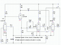
Here is mine, schematic in 2 parts.
2 loops, one to anodes of the pentode drivers from anodes of output tubes, and the second one - from secondary to cathode of the input pentode (not drawn, but it is a resistor from the secondary of the OT to the cathode). And thanks to the last, global, feedback loop, cathode voltage follows by the control grid voltage, so grid to cathode input voltage as the result is pretty low.
2 loops, one to anodes of the pentode drivers from anodes of output tubes, and the second one - from secondary to cathode of the input pentode (not drawn, but it is a resistor from the secondary of the OT to the cathode). And thanks to the last, global, feedback loop, cathode voltage follows by the control grid voltage, so grid to cathode input voltage as the result is pretty low.
Attachments
")
The input signal swing of each leg of the differential driver stage will need to be the voltage swing at the grid of the output stage required to drive the output stage to full power, divided by the gain of the differential stage. If feedback is applied at the differential stage, the gain of the differential stage is reduced by the factor of feedback applied.
Example with mostly made up numbers:
GU50 is biased at -30V grid with respect to cathode. Thus 30V peak signal swing on each driver leg output is required to drive each GU50 to full power. 30V peak is 21V RMS.
The gain of each leg of the differential driver stage is 25.
You apply 7 dB plate to plate feedback. 7 dB is a factor of 2.24.
So input signal swing at each grid of driver stage will need to be the following amount to drive the output stage to full power:
21/(25/2.24) = 1.9V RMS.
You can continue to work backwards through the remaining stages to find the input sensitivity of the amp that is required to drive the output stage to full power. The concertina has a gain of slightly less than unity, so for now, it can be ignored.
If you want an input sensitivity of 0.5V RMS, using the above partial example, you would need a voltage amp gain of 1.9/0.5 = 3.8x.
Now plug in actual numbers from your design and see where it falls.
Maybe this is what you were asking?
Plate to plate feedback will not affect the input voltage range of the driver stage. In fact it could make things worse by reducing the gain after the point where you hav a restricted dynamic range. However, a device having an input range of 2.5V does not necessarily mean that the circuit will have an input range of 2.5V; many circuits have some built-in feedback or share the input. For example, an LTP made from two devices each handling 2.5V will be able to handle 5V.
I think you need to take a step back and design the gain profile for your amplifier. Make sure you understand how each type of feedback works.
I think you need to take a step back and design the gain profile for your amplifier. Make sure you understand how each type of feedback works.
- Status
- This old topic is closed. If you want to reopen this topic, contact a moderator using the "Report Post" button.