Hello all, this is my first post here.
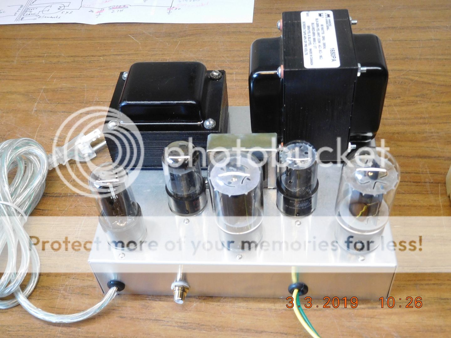
I bought a nice 1952 Browning RJ-12B tuner several years ago, so decided to build an amplifier and make a radio. I started with a power transformer from a Stromberg-Carlson radio, but bought a nice new audio output transformer. The amplifier works and sound nice, but every now and then it will put out a low frequency signal (even with no input) which causes the low frequency speaker cone to move back and forth at what I timed to be 1 or 2 cycles per second. Any suggestions?
Yesterday, I changed the input filter capacitor to 40 MFD, but that did not help.
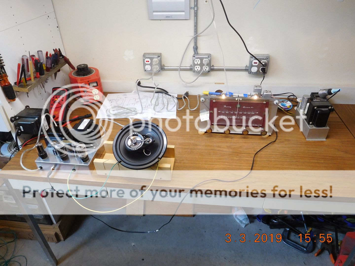
With the Browning tuner and Renegade speaker I intended to use:
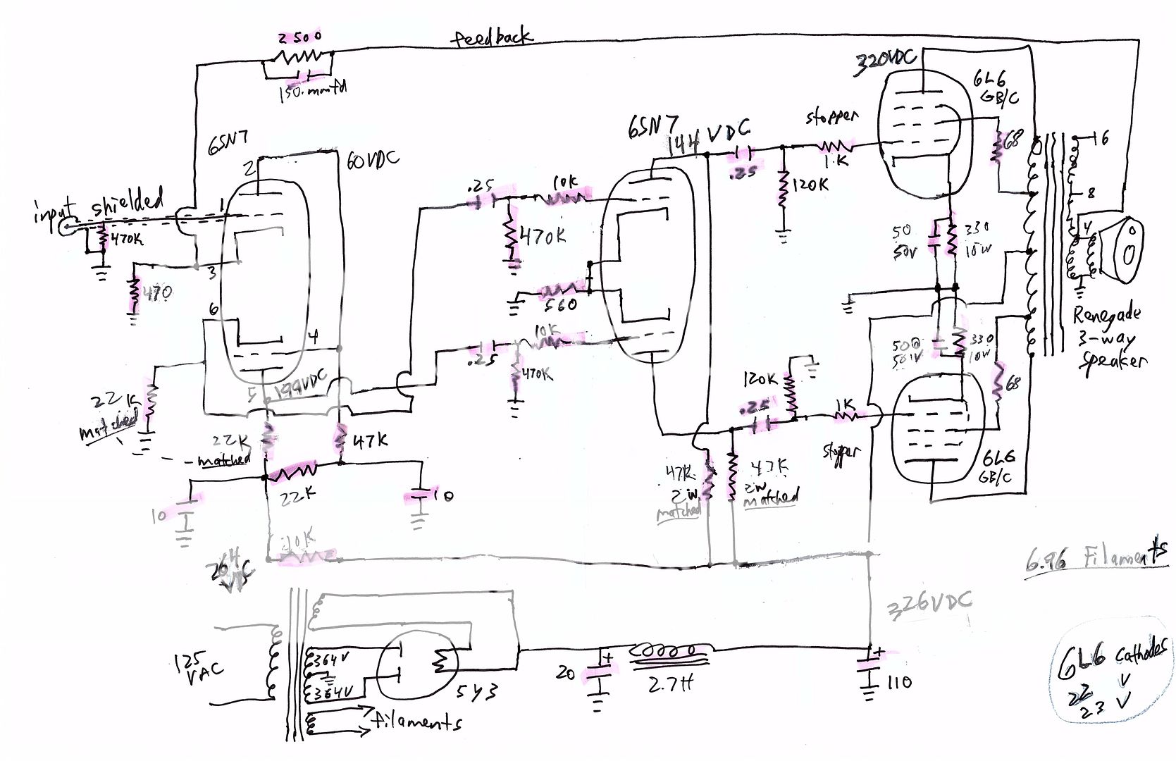
The schematic


Last edited:
I presume you are aware of the term 'motorboating'. Perhaps that term may describe your problem?
Motorboating (electronics - Wikipedia)
Motorboating (electronics - Wikipedia)
How did you determine the feedback network? You may have too much feedback, or the 150pF cap across the feedback resistor may not be appropriate for the transformer and may be causing the motorboating. Try removing that cap and see if the motorboating continues. You may have to reduce the feedback to get the amp to settle down. If anything, I would *reduce* the input cap to 10uF. That 5Y3 is also a little underspec'd for the job. You'd be better off with a 5R4. And if your filament voltage is really 6.96 like the drawing says, that's *way* to high and might be causing problems.
every now and then it will put out a low frequency signal (even with no input) which causes the low frequency speaker cone to move back and forth at what I timed to be 1 or 2 cycles per second.
The circuit may be only conditionally stable. You could try changing the amplifier's driver grid coupling caps from 0.25uF to 0.05uF.
If you prefer, try increasing the gain instead, by increasing the value of the nfb resistor from 2.5k to at least 5.1k.
Last edited:
You have Lots of low frequency phase shift network points.
Coupling caps and grid resistors. Bypass caps across Cathode self bias resistors. Output transformer primary inductance.
Just for a quick and dirty way to check the output tubes cathode bypass cap values, connect the cathodes together (2 cathodes, 2 self bias resistors, 2 bypass caps). No, I do not like to use common self bias resistors. But if the oscillation quits, we simply go back to separate cathode self bias resistors, and try much larger bypass cap capacitance.
Also, those tow 10uF B+ decoupling caps for the input stage seem a bit small to me. Try 50uF or 100uF.
With all those tubes on a common filament supply, you should build a pseudo center tap, and AC ground it.
A couple of resistors from the secondary leads to ground, say 100 Ohms each. Or better yet, elevate the filament supply to 60V with a resistive divider off of B+, and a filter cap to ground. That is better for the concertina stage.
Too much phase shift and negative feedback go together like a square peg in a round hole.
Last edited:
There are certainly many aspects that can affect the low frequency stability phase margin for that Williamson style circuit.
Even with the original Williamson, and a good output transformer, and good setup, there can be some peaky gain down around 1-2Hz, which was typically managed by ensuring that subsonic signal content was well attenuated before it got to that main amplifier.
Adjusting the output stage for accurate balance can avoid a drop in output transformer primary inductance. Having matched CR coupling part values can help. I'd recommend retaining the circa 10uF decoupling to first stages, as they are designed to provide some phase lead. You aren't using the same filtered power supply scheme as the Williamson, which may also be influencing your situation.
You may have unknowingly purchased an output transformer that is not adequate for its use in a Williamson - if so, then you aren't the first, and hence have to either battle to improve your situation, or purchase a better output transformer.
Williamson succumbed to adding a high frequency shelf network on the first stage anode to ensure stability by dropping loop gain from the top of audio bandwidth (circa 20kHz), when he provided his 'new' amplifier update after some users observed instability. The addition of a low frequency shelf network (as used by Partridge, Roddam and GEC) can do similar loop gain droop below circa 30-50Hz, and could improve your situation.
If you make changes, then it is still likely to be hit or miss, without some effort to characterise/measure the low frequency response before and after each change. If you have an X-Y scope, then that may be the easiest way to 'see' the level of phase/gain down at very low frequencies, as most meters and other techniques may not suit. But you are in the 'deep end' of the pool !
Were you following an amplifier design or magazine article or ?
I appreciate all of you jumping-in the help!
The output transformer is a new Hammond 1650PA: http://hammondmfg.com/pdf/EDB1650PA.pdf
I started this project by stripping-down a spare radio chassis to just the audio output stage and used the radio speaker. It had two 6V6 tubes and worked, but B+ was too high for 6V6 tubes. No problem, I've got 6L6GB&C tubes. I then started studying amplifier designs.
I tired disconnecting the negative feedback, and if anything, that made it worse.
I tried it with just one 220MFD capacitor and resistor for both output tube cathodes, but that did not help. I put it back to separate cathode resistors, but with the capacitors on each increased to 220MFD. No improvement.
I replaced the 10MFD capacitors with 47 MFD capacitors, but that does not help (nor seems to hurt).
Finding the article I'd previously read about stopper resistors, I added a 10,000 ohm stopper before the input grid. I also added a 400MMFD capacitor from there to ground to prevent ringing. Seeing that many other designs use a 1 Meg. resistor from the input to ground, I changed the 470,000 ohm resistor I had there to a 1 Meg. unit.
Perhaps I need to install a balancing rheostat, something I see on quite a few of the amplifier designs, and some old radios.
As the above posts said - and every person will have his own set of suggestions!!
Yes, the original Williamson showed a suspicious peak at the low frequency end. I also frown at the coupling time constants to be both around 2 Hz. Why that low?? One does not want to fiddle with a classic design, but the member does have a problem.
As said by others, my first problem would be with an unknown output transformer (primary inductance and such.) If I were to experiment I would greatly reduce the -3 dB frequency of at least one of the coupling RCs. This by about x10, say the first ones to C=.027µF and R=470K. Then I am also loathe to bring h.t. decoupling into the mix although they may be designed to act as T Robbins said. In these days of physically quite small electrolytic caps I never use under 47µF and often >100µFto get those out of the stability scene. (Tube characteristics showing an unacceptable spread these days, further interferes with stability at the l.f. end with push-pull.)
But as all agreed the member is thrown in at the deep end! The use of a signal generator and 'scope would be valuable to look at what exactly goes on at the low end.
I wish you good fortune!
P.S: I wrote my post before reading the previous one by he OP. Still
Last edited:
Okay, now that I understand the schematic, I see it's a Williamson. I agree with Tim and Johann. You should not have separate bias resistors for the output tubes. You probably can get this stable. It looks like you're following the 1953 Hafler/Keroes design. Go back and try to get closer to it. The feedback capacitor will probably not work with that output transformer unless you know how to tune it with a 'scope. Try leaving it out and see if the amp stabilizes. And you really should swap out that 5Y3 for a 5AR4. At 320V B+, the circuit is running way under spec and that may be part of your problem.
https://dalmura.com.au/static/Radio-News-1953-02.pdf
https://dalmura.com.au/static/Radio-News-1953-02.pdf
OP, were you able to set up the feedback for 20dB?
Were you able to confirm the output stage cathode resistors were within 1-2% tolerance? Given the 22/23V cathode measurements, the cathode currents may still be more than 5% different, which can have an influence at idle, although likely not the big ticket issue here.
The 1650PA spec shows a good level of primary inductance, but at a large signal voltage of 240V rather than the 5V level used by Williamson, and commented on in his articles as the test level that is of most influence for low frequency performance.
Does your radio have an output stage that attenuates signal below say 50Hz, and is it capacitor coupled to the power amp? You may get some benefit from increasing that attenuation, to reduce the level of any low frequency signal/disturbance that could start the amp oscillating.
Your chassis is pretty tight, which doesn't allow a roomy layout of parts, and so you may experience coupling from high voltage signals (eg. the wiring to and from the rectifier valve) to the input valve sitting very close nearby. Your other wiring and layout decisions may also make the amp more susceptible to quirky behaviour, as unfortunately for you, the Williamson circuit can be very unforgiving for parasitic couplings that are not easy to appreciate if you aren't carefully following a published layout.
Without the high frequency step-network mod, and given your layout, and the unknown output transformer performance at high frequency, you run the risk of high frequency oscillation as well - which could go unnoticed or noticed by some quirky outcome like a blown tweeter.
Interesting, I had thrown away the various articles I'd previously found, so searched today and found that article by David Hafler and Herberrt I. Keroes earlier today. It is one I'd not previously seen and it is interesting.
Thanks! A 5AR4 only drops 17 volts, while a 5Y3 drops 60 volts. I could use solid-state diodes, but want it to be like what somebody would have built in the 1950s to go with the nice Browning tuner.
I dropped and broke one of my only 6SN7 tubes while testing, so will get a new one and a 5AR4 before I can resume testing.
I had it running before I broke one of the 6SN7s, and it was stable. I then connected the tuner, that got it started with the low frequency cone movement. Even after I turned the tuner off, the low frequency cone movement continued! So, it seems it needs to be triggered...
Three of the articles / schematics I had previously found most interesting are:
Design for a 50 Watt Amplifier
https://www.bonavolta.ch/hobby/images/audio/6l6.gif
The Valve Wizard
Yeh, that 1957 WW article utilises the low frequency shelf network (stabilising section of text) as described by Roddam in the refs. It also uses a shunt type network for shelving higher frequencies - equivalent to the first stage Williamson anode load shunt network that was an addition. Those two 'stabilising' networks make such an amp a lot more immune to quirks when feedback is used.
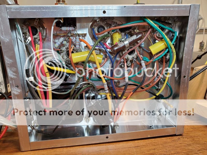
It could be nothing to do with this, but your layout and construction could be better. It's a bit hard to see what's what but a few things to note,
1) Heater wiring should be twisted and shoved into the corners of a chassis and shouldn't be floating.
2) Big caps should be secured so they arn't "flapping around in the breeze" as Dave Jones says.
3) Resistors especially grid R's should have as little lead length as poss when connected to valve bases.
4) Particular attention should be given to grounding, grounds should be electrically and mechanically sound.
5) wiring should be neat and tidy, things to note, wires in and around the PSU should be short, obviously well insulated.
There's other "rules", but these are some of the main ones
Your problem could be down to none of these things, but when trying to fault find intermitent problems and oscillations, if your construction is good it's one less area you have to worry about.
Andy.
When looking at the original circuit two things struck me:
1. very high feedback - could be unstable
2. rather high grid coupling capacitor values - this could lead to two problems:
2a. LF instability
2b. mains voltage variations being fed straight through the amp
You said that removing the feedback made the problem worse. This suggest that LF loop instability is not the problem (although it may turn out to be another problem once you have solved the first problem). I suspect mains voltage variations. These can occur at frequencies from around 1Hz downwards, so you need to ensure that your amplifier has little gain below the audio band.
Last edited:
Interesting, I had thrown away the various articles I'd previously found, so searched today and found that article by David Hafler and Herberrt I. Keroes earlier today. It is one I'd not previously seen and it is interesting.
Thanks! A 5AR4 only drops 17 volts, while a 5Y3 drops 60 volts. I could use solid-state diodes, but want it to be like what somebody would have built in the 1950s to go with the nice Browning tuner.
I dropped and broke one of my only 6SN7 tubes while testing, so will get a new one and a 5AR4 before I can resume testing.
In reality, the 5AR4 will drop about 40 volts in that circuit. With a 365-0-365 power transformer and a 10H choke, you should get about 430-440 volts, which is close enough to the original to run the circuit within spec.
Whatever you used to model the amp, you are extremely close to the Hafler/Keroes Williamson, which uses the same value coupling caps and a 6.6K output transformer, so I would use that as a basis to try to get the amp working as well as possible.
I just ordered a larger chassis and will redo it with the heater wires solid, not stranded, so I can get them down onto the chassis. I was originally planning to put it in a smaller cabinet, but now plan to make a new floor-standing console cabinet.
This is the first electronic thing I have built, and it is an interesting project.
This is the first electronic thing I have built, and it is an interesting project.
I notice that there's no decoupling between output stage B+ and push-pull driver stage B+. This is not good practice and should be remedied. DTN Williamson used another choke, but its resistive losses are what's needed most, and a simple resistor will do. A K-Ohm or two should do. And a big capacitor to ground - caps are cheap now; no reason to stint.
I'd personally recommend much smaller coupling caps feeding the output stage grids. Maybe smaller than 0.1 uF.
All good fortune,
Chris
I'd personally recommend much smaller coupling caps feeding the output stage grids. Maybe smaller than 0.1 uF.
All good fortune,
Chris
Last edited:
- Status
- This old topic is closed. If you want to reopen this topic, contact a moderator using the "Report Post" button.
- Home
- Amplifiers
- Tubes / Valves
- Occasional low frequency problem