Thanks, Chris!
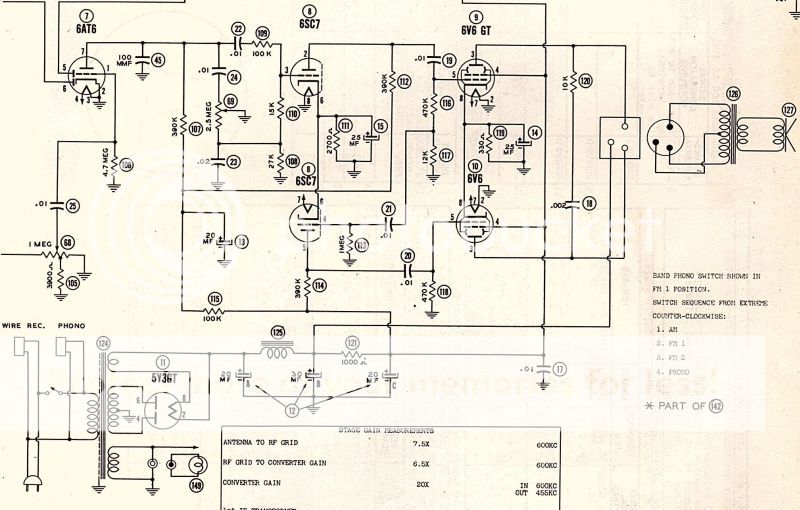
1) Here is the output and power supply section of the Stromberg-Carlson 1210H I started with, and it has such a decoupling resistor. I'd installed it in my amplifier, but thought it did nothing, so removed it. Now I'll put it back.
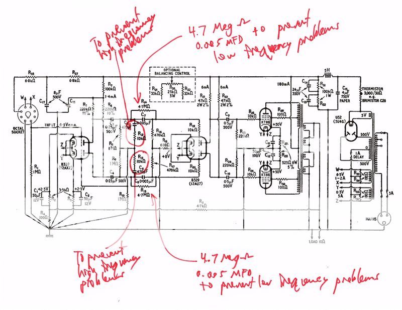
2) Several people here and on antiqueradios.com have recommended smaller coupling capacitors. I respect and appreciate that, but wonder why Messrs. Heath and Woodville who wrote the April 1957 article in Wireless World (starting on page 158, see American Radio History) "Design for a 5-Watt Amplifier" 0.25MFD coupling capacitors between the first and second tube, and 0.5MFD units between the second tube and the output tubes? One of the guys on antiqueradios.com even showed charts of the benefits of going to much larger capacitors - 0.68 between the first tubes, and 2.2 to the output tubes.

Last edited:
The 88-50 circuit uses a low frequency shelf network which alleviates the need to carefully manage the various low frequency high-pass CR filter networks that influence how stable the amp is.
The topic gets complex, but can be waded through, and although CR network and shelf network response can be calculated from part values with good accuracy (or even by simulation nowadays rather than ruler and graph paper), the simplified RL network presented by the output stage plate resistance and primary winding impedance is anything but simple, and can be the cause of oscillatory response if so inclined. The link below goes through a detailed description for the Williamson circuit:
https://dalmura.com.au/static/Williamson%20design%20info.pdf
Last edited:
If you're familiar with op-amps and Bode (magnitude and phase vs. frequency shown together on the same x-axis) plots, you'll know about dominant poles. If anyone's not already familiar with op-amp models, I can highly recommend a quick glimpse at the basics (which is all you'll need) for the power and understanding it gives to the very non-ideal amplifiers that are valve amplifiers. There's one serious limitation: op-amps are DC coupled, so nobody much discusses low-frequency stability. Ain't none.Several people here and on antiqueradios.com have recommended smaller coupling capacitors. I respect and appreciate that, but wonder why Messrs. Heath and Woodville who wrote the April 1957 article in Wireless World (starting on page 158, see American Radio History) "Design for a 5-Watt Amplifier" 0.25MFD coupling capacitors between the first and second tube, and 0.5MFD units between the second tube and the output tubes? One of the guys on antiqueradios.com even showed charts of the benefits of going to much larger capacitors - 0.68 between the first tubes, and 2.2 to the output tubes.
But the same requirements and the same solutions apply, flipped left for right on the x-axis. A dominant zero (just like a pole, but flipped on the x-axis) for low-frequency loop stability should also be some distance (on the frequency = x-axis ) above the nearest other zero.
The other main consideration is overload recovery time. Clipping in an optimized amplifier like yours should occur when the output valves' grids are driven into conduction. Positive of the cathode, they conduct, the RC network around them is charged and output valve bias is disturbed. The extra charge bleeds down at a rate set by the product of R and C. The smaller the C here, the faster the amplifier recovers, so this is the best place to put your dominant zero. I'd suggest trying something fairly high, maybe 16 or 20 Hz, just as an experiment, but you'll likely end up around 8 or 10 Hz out of fear that you might be missing something.
Feedback amplifiers of the 1950's were largely ad-hoc, although sometimes well measured. Lots of folks today try to get by on ad-hoc solutions. OTOH, DTN Williamson understood the issues very deeply, but pushed hard against the limitations of his day, making a high performance, but demanding design. It's an expert's amplifier, but beloved by amateurs. Quite a legacy.
All good fortune,
Chris
I'm almost 62 and did not have time or money for electronics in high school, although I did have calculus, physics, chemistry and was student body president. I started with the electronics hobby in 2008 and am largely self-taught, with help from others in clubs and on forums. An Op-Amp, as far as I know, is some sort of transistor / integrated circuit gizmo. I've forgotten some, perhaps much, of the math I've not used for 40 years, but not the framework for understand it. The people involved with electronics in the 1920 to 1950s had to use slide rules (yes, I had one in high school, before I got a Texas Instruments SR 51) and such, so their achievements were certainly not easy.
The first op-amps were made with vacuum valves. (If you ever find a really good ECC83 Amperex or Telefunken marked G.A.P. it came from an op-amp.) But the internals aren't interesting; op-amps are useful as a simplification allowing attention to be paid to stuff that matters and as a way of modeling. Understanding comes with a useful model.
I've tried to suggest this several times on this forum, and have been universally told it's too much trouble to learn the basics. I'm considerably older than you, entirely self taught, and not the sharpest pencil in the pack. A geometric solution works well for me and I believe would for everyone else playing around with high performance loop feedback amplifiers. The fancy math can come later, IMO.
All good fortune,
Chris
Yes the 470pF-10k is a shelf network with equivalent action to when Williamson put a 200pF-4k7 network across his 47k first stage plate load. But here the shelf network is placed after the phase splitter and so has to act on both phases (and hence twice the number of RC's).
It is a shelf network, so likely starts acting just at the top of the audio band, and then drops gain, but plateaus out at some higher frequency, rather than keep dropping gain.
References by Learned, and Roddam, are worth reading for general info as well as detailed design.
https://dalmura.com.au/static/corrective%20networks.pdf
https://www.americanradiohistory.com/Archive-Wireless-World/50s/Wireless-World-1951-03.pdf
12AX7 rp = 60k Ohm, that drives: RL 220k Ohm and 0.25uF driving 1M Ohm (at high frequencies, 0.25uF is a very low impedance). and 0.005uF in parallel with 4.7M Ohm drives 470k Ohm (0.005uF = 5000pF, which is more than 10X the 470pF in the pole)
At high frequencies, we have these in parallel: 60k 220k 1M 470k = 41k
The 10k & 470pf high frequency pole is in parallel with 41k
470pf = 41k Ohms at 8260Hz.
You can see that the pole does cut the high frequency response by about 3 dB at 10kHz, the 10k Ohms determines the final gain at high frequencies. The Dyna Stereo 70 had a high frequency RC pole at about 7kHz, but that is with a different output transformer, and different negative feedback.
Last edited:
So a "pole" is kind of a barrier or threshold, kind of a soft low pass or high pass filter? I'd never read the term "pole" before now.
A slightly larger chassis came, so I can get going with building Version II of this amplifier. The old power transformer was running hot, significantly more so than what seems normal for radios, so I finally decided to buy an Edcor XPWR011.
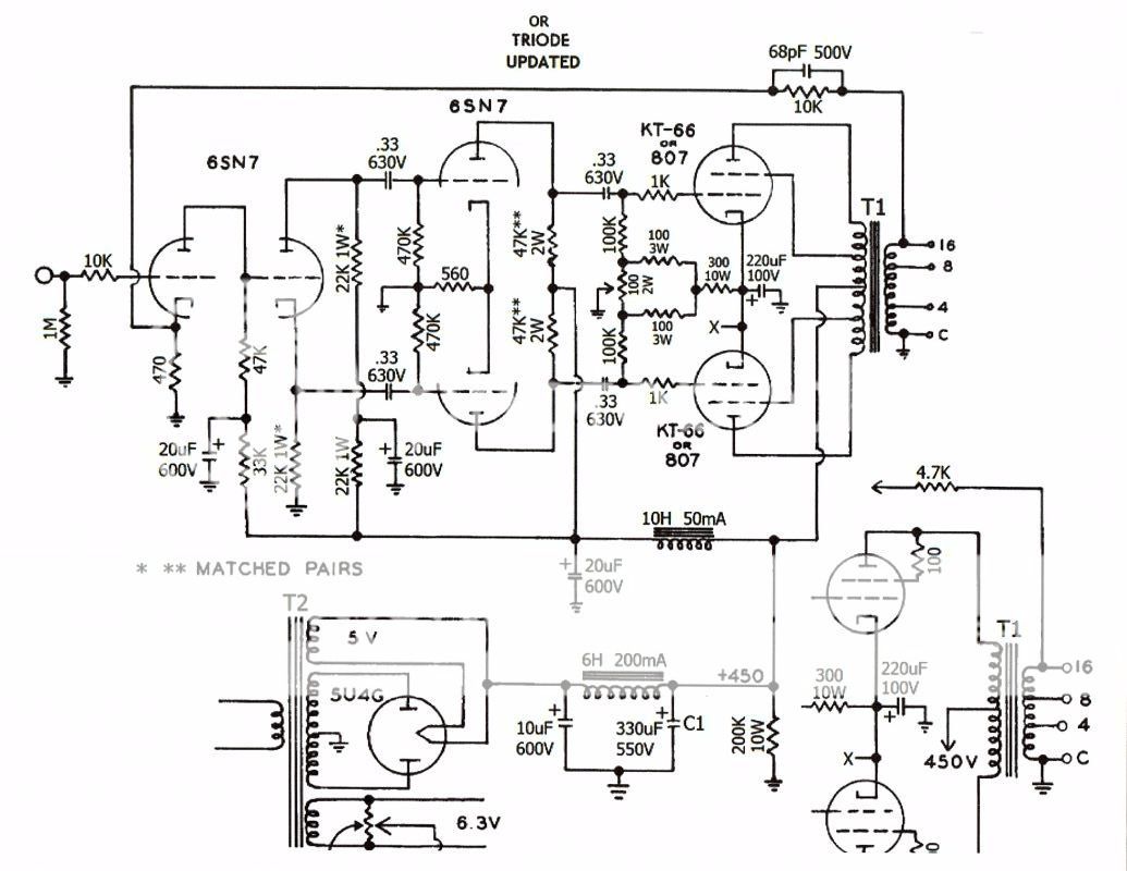
I found another of the schematics which I'd found and studied before building Version I of this amplifier:
A slightly larger chassis came, so I can get going with building Version II of this amplifier. The old power transformer was running hot, significantly more so than what seems normal for radios, so I finally decided to buy an Edcor XPWR011.
I found another of the schematics which I'd found and studied before building Version I of this amplifier:

So a "pole" is kind of a barrier or threshold, kind of a soft low pass or high pass filter? I'd never read the term "pole" before now.
A slightly larger chassis came, so I can get going with building Version II of this amplifier. The old power transformer was running hot, significantly more so than what seems normal for radios, so I finally decided to buy an Edcor XPWR011.
I found another of the schematics which I'd found and studied before building Version I of this amplifier:
Do you know where you found that schematic? It's a modification of an Acro circuit. I'd be interested to know who modified it and why. Thanks!
ETA: Never mind, I found it!
Acrosound KT66/807 Ultra-Linear or Troide Amplifier Circuit
Last edited:
search there: 100 Amplifiers – Part 1 , 1916 – 45 | Lilienthal Engineering
there are 4 pages of schematics but I do not have time to look now.
there are 4 pages of schematics but I do not have time to look now.
acrosound or craftmen c500 redesigned
Yes, it's an Acrosound, "redesigned" by some random hobbyist. The .25uF coupling caps were changed to .33 because ".25 are hard to find"! The guy doesn't specify any particular output transformer, *maybe* an Edcor, and says a single 8 ohm tap will work "without upsetting the feedback arrangement." Well, no, it won't--it will reduce the feedback considerably. I doubt he actually built this.
Indeed, that comment about 0.25 capacitors being hard to find was humorous, as was his comment about using a 5U4G because it is still in production while the other rectifier tube is only available NOS. His site states that he was a broadcast engineer. I like the way he drew his schematic. I do see that most of the designs include some sort of balancing control, so I will have one in Version II of the amplifier.
Yes, it's an Acrosound, "redesigned" by some random hobbyist. The .25uF coupling caps were changed to .33 because ".25 are hard to find"!
I don't understand.Indeed, that comment about 0.25 capacitors being hard to find was humorous
0.25uF is no longer a standard value, unlike 0.22uf and 0.33uF
30 seconds at the Digikey website produced these results for film capacitors:
0.22uF 2178 choices
0.33uF 1872 choices
0.25uF 26 choices
I don't understand.
0.25uF is no longer a standard value, unlike 0.22uf and 0.33uF
Not to mention 0.27uF.
- Status
- This old topic is closed. If you want to reopen this topic, contact a moderator using the "Report Post" button.
- Home
- Amplifiers
- Tubes / Valves
- Occasional low frequency problem