Why not use 6N14P as it's designed for cascode service?
6N14P - Wikipedia
They are great tubes IMHO.
6N14P - Wikipedia
They are great tubes IMHO.
It's supposedly equivalent to the ECC84
https://frank.pocnet.net/sheets/030/e/ECC84.pdf
I'm not running cascode per se, but one section as an active load for the other, 260V B+ so 130V per section. I think the current is set around 8mA, and I never elevate heaters or had a failure related to heater/cathode voltages. YMMV")
https://frank.pocnet.net/sheets/030/e/ECC84.pdf
I'm not running cascode per se, but one section as an active load for the other, 260V B+ so 130V per section. I think the current is set around 8mA, and I never elevate heaters or had a failure related to heater/cathode voltages. YMMV
Last edited:
Whoa, those curves look as linear as 6N6P but without the excessive current. Thanks!Why not use 6N14P as it's designed for cascode service?
6N14P - Wikipedia
They are great tubes IMHO.
OK, I am back in business!!! I have 2 good 10k Fisher output transformers (actually, I have 5) and 3 good PT’s out of Fisher 400’s. My chosen chassis is this bad boy:


I really like this 40’s industrial look.
The advantages are that it has TONS of room both above and below the deck, which I’m going to need because this is my first amp from the ground up. The choice of transformers is goo too, because they all sit above the deck rather than sit down below the waterline, which would require me to cut large holes in the deck, which i don’t want to have to do.
The disadvantage is that I’ve got just 7 sockets to work with, all octals. I CAN repurpose the hole for the can cap as an 8th socket (there is plenty of room below deck for all manner of electrolytics).
The output tubes will be octals (I am strongly leaning towards the 6n3c’s). That leaves 3 sockets left - two drivers/phase inverters and 1 pre-amp tube. Which MEANS I’d have to use solid state rectification, unless i want to repurpose the can cap hole or get put the chassis punch. Which is a shame no matter how you look at it.
ALL of the circuits above look doable. I just need to settle on one. I am NEW, and this will be a first project (I have done some rehabbing tho). The trick is octal drivers and pre-amp. I COULD buy socket converters (and new novols). But not my preferred option.
Actually, the high voltage secondary of the Fisher 400 PT does not have a center tap. Which necessitates that I use solid state rectification in any event, doesn’t it?
If I remember correctly, the Fisher 400 used a voltage doubler configuration. You could probably do tube rectification, but I think it would require multiple tubes. SS diodes are considerably easier and IMO a better choice. I want to say the Fisher 400 PT has a 160v secondary.
It depends on frequency too. A 50W OT @50Hz will work pretty satisfactory at 100W @ 100Hz as the induction in the core is the same.
For same induction: 50W @ 50Hz is 200W @ 100Hz.
Induction goes as voltage. Power goes as square of voltage.
I do not agree that 6L6GC will "over-power" this iron. If used at the same B+, no real difference. If B+ is raised to exploit the higher rating of 6L6GC, THD at the lowest useful frequency will rise, or for same-THD the lowest full-power frequency must rise. But only about 1.22X, say 50Hz to 61Hz. And you can always just not play it so loud the deep bass splatts.
If I remember correctly, the Fisher 400 used a voltage doubler configuration. You could probably do tube rectification, but I think it would require multiple tubes. SS diodes are considerably easier and IMO a better choice. I want to say the Fisher 400 PT has a 160v secondary.
Well, this voltage doubler business is a fly in the ointment. I’ve been studying tube rectified PSU’s for a bit now, and I think i understand them. I was even going to add a choke. I was prepared to convert over to a solid state rectifier (which I thought would be a full wave bridge), but this voltage doubler business (which I have looked up) is baffling!!
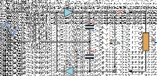
Does this look like a voltage double situation (I can’t tell):

I’m even a little iffy on how they accomplish the rectification with just two diodes (and one goes to ground).
Well, this voltage doubler business is a fly in the ointment. <snip>
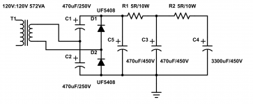
Looks like it. Personally, I think that when drawn that way, it's very difficult to see what's going on. SUPER convenient to draw a schematic that way, but not the easiest to understand if you aren't familiar with voltage doublers. Attached is an image that IMO makes more sense (I do not own the rights to this image, BTW. All credit goes to Electronics Tutorials).
The way I've always thought about it, which may or may not be correct, is that the capacitors are being charged in parallel and discharged in series. One diode does go to ground, but in reality it is going to the negative side of the filter cap which just so happens to be the ground reference for the rest of the circuit. From the capacitor's perspective, one of the transformer leads is zero volts, but from the rest of the circuit's perspective, the negative side of the filter cap is zero volts.
Hopefully that clears things up.
Voltage doublers are a very handy circuit, and they work extremely well. They were very common back in the day because it was easier to make a 160V @ 700mA winding reliable than it was to make a 750 VCT @ 150mA reliable, due to the gauge of the wire. At least that's what I've been told.
Other major amps that used it included the HK Citation II, Heathkit AA-121, and countless others. These were not cheap amps, especially the Citation II.
The cool thing about them is that you can get a ~320V DC supply from a standard 120V isolation transformer, which are quite economical (do not even think about doing it without the transformer, as that is extremely dangerous). Eli Duttman's El Cheapo uses a Triad (N68?) transformer in this configuration, and I know it's one of my favorite for preamps because it can cut the cost of the PT dramatically when you can use a jellybean 120:120 transformer.
Attachments
That exact doubler plan worked for thousands of Bogens, even the 2*150W beast.
Wrapping your head around it is good training.
It speaks to a time when high voltage diodes were eXpensive. The Doubler needs only half the PIV, and only two of those. OTOH it needs two caps. OTOH it gives a half-voltage tap which may be handy (the Bogens used 600V on plates and 300V on screens).
Wrapping your head around it is good training.
It speaks to a time when high voltage diodes were eXpensive. The Doubler needs only half the PIV, and only two of those. OTOH it needs two caps. OTOH it gives a half-voltage tap which may be handy (the Bogens used 600V on plates and 300V on screens).
Last edited:
the full wave doubler is a good rectifier configuration, i use it lots of times in my tube amp builds..i can not understand why people are afraid to use them and give them a bad rap...
the two diode voltage doubler and the 4 diode full wave bridge has the same transformer utilization, i.e. the full 360 degrees of the electrical cycle is utilized to deliver current, unlike in the full wave center tapped rectifier where each diode contributes current for just 180 degrees, half of the time doing nothing...
another thing going for the voltage doubler is the ease of construction, since much lower voltages are involved, less creepage protection is needed, insulation requirement is much simpler for say a 200 vac winding than than say an 800vac ct winding..
as with anything electronics, the full wave doubler can be engineered to deliver the goods...
lots of Japanese tube amps use them and so with the harman kardon citatiion 2..
The typical voltage doubler does pull current from the transformer on every half cycle. It however charges each "doubling cap" only on one half cycle, then it charges the other one. The output is drawn from the two caps which are in series. Therefore the output cap is fully refreshed only once per complete cycle. The regulation in such a circuit can be worse than the typical full wave bridge or full wave center tapped circuit unless large caps are used. This is most important when cheap transformers (higher DC resistance) are paired with a circuit with widely varying current demands, like a near class B overdriven guitar amp.
One day several years ago I set out to minimize these issues, and came up with the "way too many diodes" power supply. I did this to minimize cost and size, but the circuit can be used with good parts to build a better doubler if so inclined. It looks somewhat complicated but it is basically two of the usual voltage doublers wired such that they are operating out of phase so the output cap gets charged on every half cycle. I also added the pair of diodes needed to create a full wave bridge so that I get two power supply voltages from the transformer, one at about 1.3X the transformer voltage, and one at 2.6X the transformer voltage. Using a common 120 to 120 vvolt isolation transformer on my highish 125 volt line gets me about 165 to 170 volts and 330 to 340 volts.
The schematic of the complete amp is included. The power supply is at the top. The low voltage output feeds the screen grids of the 45B5/UL84 output tubes and powers all the heaters which are wired in series. The high voltage output powers the plates of the output tubes and the entire preamp section which turned out to have way too much gain.
Attachments
The typical voltage doubler does pull current from the transformer on every half cycle. It however charges each "doubling cap" only on one half cycle, then it charges the other one. The output is drawn from the two caps which are in series. Therefore the output cap is fully refreshed only once per complete cycle. The regulation in such a circuit can be worse than the typical full wave bridge or full wave center tapped circuit unless large caps are used.
Back in the early 90s my father addressed this issue by simply acquiring a pair of 2900uF 250V Sprague Powerlytic caps at surplus. Each about the size of a soda can. A bit unsightly though, and super expensive if you had to buy them new. Tubelab's solution is better.
Whoa . . . That’s complex. This is my first build. I’ll be utilizing the voltage doubler circuit, but will have to keep things simple. I’ve wrapped my head around the concept now and think i understand it.The schematic of the complete amp is included. The power supply is at the top. The low voltage output feeds the screen grids of the 45B5/UL84 output tubes and powers all the heaters which are wired in series. The high voltage output powers the plates of the output tubes and the entire preamp section which turned out to have way too much gain.
- Status
- This old topic is closed. If you want to reopen this topic, contact a moderator using the "Report Post" button.
- Home
- Amplifiers
- Tubes / Valves
- Selecting an output tube . . .