How many Ohms is the signal generator output? How many volts is the signal generator output? Can you measure the secondary output accurately? Scope, or DMM that can work well at 1kHz.
A 600 Ohm generator should be able to overcome the resonance of the primary inductance and distributed capacitance of the winding. That is often in the 500Hz to 2kHz region. A 600 Ohm generator will not work well for this if the signal generator is set at 100Hz, the transformer inductive reactance will "get in the way".
A 10k to 8 Ohm transformer will have a 35 to 1 reduction of the generator voltage at the secondary. 1Volt on the primary becomes only 28mV on the secondary.
Ok - I think I have this working.
With my generator set to 20 volts at 60 cycles, I get this through the 8 ohm tap:

It’s 765mv (give or take). That’s 20/.765 = 26:1 winding ratio. 26^2 = 676. 676 x 8ohm = 5408. So. . . This is a 6k transformer.
So far so good.
HOWEVER, my other transformer is shot!!

Uhg. Fortunately, there are more where that came from.
Still, it’s discouraging.
I would have assumed that the multitester measured peak to peak, no?
I have to read up on peak to peak versus RMS.
I was running the generator at 60 cycles. But that was because I was not thinking. 1k would have made more sense.
Thank goodness both transformers on my other one are showing good. However, they are showing 8800 Ohms each. I assume those are the 10k. Would I be getting better numbers if I put the loads on the output taps like you suggest above?
With my generator set to 20 volts at 60 cycles, I get this through the 8 ohm tap:
It’s 765mv (give or take). That’s 20/.765 = 26:1 winding ratio. 26^2 = 676. 676 x 8ohm = 5408. So. . . This is a 6k transformer.
So far so good.
HOWEVER, my other transformer is shot!!
Uhg. Fortunately, there are more where that came from.
Still, it’s discouraging.
20V peak to peak is 7.07Vrms. I bet your generator 20V is into a high impedance load. And many DMMs and similar are high impedance. Does that say anything about what you got? "Making Calibrated Measurements since 1959" - Me
I would have assumed that the multitester measured peak to peak, no?
I have to read up on peak to peak versus RMS.
How many Ohms is the signal generator output? How many volts is the signal generator output? Can you measure the secondary output accurately? Scope, or DMM that can work well at 1kHz.
A 600 Ohm generator should be able to overcome the resonance of the primary inductance and distributed capacitance of the winding. That is often in the 500Hz to 2kHz region. A 600 Ohm generator will not work well for this if the signal generator is set at 100Hz, the transformer inductive reactance will "get in the way".
A 10k to 8 Ohm transformer will have a 35 to 1 reduction of the generator voltage at the secondary. 1Volt on the primary becomes only 28mV on the secondary.
I was running the generator at 60 cycles. But that was because I was not thinking. 1k would have made more sense.
Thank goodness both transformers on my other one are showing good. However, they are showing 8800 Ohms each. I assume those are the 10k. Would I be getting better numbers if I put the loads on the output taps like you suggest above?
There are many kinds of AC meters.
AC signals are not always pure sine waves.
1. Some AC meters respond correctly to Peak Voltage.
2. Some AC meters respond correctly to the Average of Rectified Voltage
3. Some AC meters respond correctly to the RMS of the Voltage
But most often, most AC meters are Calibrated to read out the RMS voltage of a pure sine wave. If the meters of 1., 2., and 3., are calibrated to read out rms of a pure sine wave, they all will read the same on a pure sine wave. But they, 1. 2. 3. will all read out with different answers for any signal that is not a pure sine wave. A triangle wave will give you 3 different answers when you use meters 1. 2. 3.
I believe you meter is calibrated to correctly read out in RMS of a pure sine wave (60Hz yes; 1kHz maybe, 20kHz probably not).
Try using the scope, 1kHz from the signal generator, and measure the primary voltage, then the Unloaded secondary voltage. Then go back to the primary voltage to be sure nothing has changed or been disturbed. Then go back and do the same as above, but with the secondary Loaded this time.
We can calculate turns ratio, effective loaded impedance, and percent power loss that way. What is the output impedance of your generator? Check the manual.
I don’t have the manual. And I can’t find it on line. I am using the scope for all measurements tho. So far so good (in a moment of panic, I checked the OPT’s on my MAC 1500 that I’m about ready to send out for rehab - checked out ok.
SO - the turns ratio I got on the last set of Fisher I did was 33:1, which is within the measuring error of your figure - 35. So I have two good 10k OPT’s. And I have one good and one bad 6k OPT. Which is too bad.
I’m going to re-measure the 6k ones again with your suggestions.
Well, I don’t have an 8 ohm load. Ha!! Probably one of my speakers would be steady at 8 Ohms at 1k!
Anyway, my “bad transformer” is giving me a better wave now, but it’s very unsteady. It kinda “undulates”. I wish I could show a video. What would cause a signal to pass (for it less the right amplitude and frequency, but have it undulate so much?
For what it’s worth i have access to a Fisher 500B in deplorable condition that may have perfectly good transformers in it. This ran 7591’s. So I should be in the same boat, so to speak.
The Fisher 400 10k primary output transformers are absolutely first rate iron. You won't have any trouble building a stable amp with these. I built a very nice 22 watt per channel amp using 7868 finals with these transformers. Some of the best measuring iron I've seen.
A "Mullard" frontend is a voltage amp coupled to a differential pair inverter. google Mullard 5-20 circuit. I used a pentode voltage amp coupled to a split load inverter on mine, with 17 dB feedback as I recall.
A "Mullard" frontend is a voltage amp coupled to a differential pair inverter. google Mullard 5-20 circuit. I used a pentode voltage amp coupled to a split load inverter on mine, with 17 dB feedback as I recall.
Last edited:
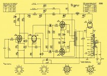
Perhaps the "best" implementation of Mullard style topology can be found in the H/K Cit. 5. Notice the high gm small signal types. The 12BY7 shown is getting scarce and is (IMO) best saved for already built units. A 6922 cascode that replaces the 12BY7 is provided.
Attachments
The Fisher 400 10k primary output transformers are absolutely first rate iron. You won't have any trouble building a stable amp with these. I built a very nice 22 watt per channel amp using 7868 finals with these transformers. Some of the best measuring iron I've seen.
A "Mullard" frontend is a voltage amp coupled to a differential pair inverter. google Mullard 5-20 circuit. I used a pentode voltage amp coupled to a split load inverter on mine, with 17 dB feedback as I recall.
Ok . . . So this is starting to coalesce. But a few questions - I was under the impression that a “power amp” generally involved just the phase splitter and the output tubes. These foresee a voltage amp before the phase splitter tho. That’s fine from my perspective because I imagine this is more appropriate for the inclusion of a volume and balance control.
I DO want these bits - so does that mean they are situated before the voltage amp, or after (ie., between the voltage amp and the phase splitter)?
I’m glad to hear the 10k transformers are worthwhile. Unfortunately, my good set was slated to remain with the 400 that I’m rehabbing. I had intended to use the other set (alas, one is bad anyway tho) for this project. I will get my hands on the set from the 500B.
Perhaps the "best" implementation of Mullard style topology can be found in the H/K Cit. 5. Notice the high gm small signal types. The 12BY7 shown is getting scarce and is (IMO) best saved for already built units. A 6922 cascode that replaces the 12BY7 is provided.
These look very doable.
And of course, there is the Williamson which is my "go to" design.
Williamson amplifier - Wikipedia
http://www.sowter.co.uk/pdf/Williamson Amplifier.pdf
Williamson amplifier - Wikipedia
http://www.sowter.co.uk/pdf/Williamson Amplifier.pdf
I was under the impression that a “power amp” generally involved just the phase splitter and the output tubes.
Not necessarily. Depends on the design.
I DO want these bits - so does that mean they are situated before the voltage amp, or after (ie., between the voltage amp and the phase splitter)?
There are several topologies that work. In a Mullard-type frontend, you would place the voltage amp before the inverter (the inverter fulfilling both duties of phase inversion as well as driver for the output stage), and if you wanted a volume control, assuming the design had enough gain for the amount of feedback you want to add, you would place the volume control in front of the voltage amp.
For example, if driving a 7868 or 7591 output stage using a Mullard type frontend, you could use a 6SN7 or 6FQ7 inverter stage with another 6SN7 or 6FQ7 voltage amp stage in front of it. This setup will provide enough gain, even with a moderate amount of feedback (say 12 dB), so that a volume pot could be utilized. The amp could then be driven from a mobile phone, for example. In this case you'd have input sensitivity of about 0.5V RMS*, which is about right in my opinion for driving with a mobile device. But if the amp had more than say 0.7V input sensitivity, I think it would be wise to use an external active preamp.
===
*Drive requirement of a 7868/7591 push pull output stage is approximately 12V RMS to deliver 22 watts output across a 10K primary load. A 6SN7 differential pair inverter/driver stage will have gain of approximately 7.5x from each output leg to ground. A 6SN7 voltage amp stage configured in common cathode arrangement will have open loop gain of approximately 12x, and with 12 dB of feedback applied, closed loop gain will be approximately 3x.
Therefore closed loop sensitivity of the amp will be:
12/(7.5*3) = 0.53V RMS.
I had intended to use the other set (alas, one is bad anyway tho) for this project. I will get my hands on the set from the 500B.
I also have a pair of 500B output transformers from a doner unit. But I haven't built anything with them yet, nor have I measured them. They are "small" though, like the Fisher 400 output iron, so I expect they are good for 25 watts.
Here's an example.
Attachments
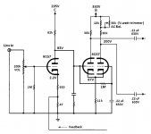
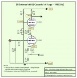
I’m having trouble with that “phase inverter” circuit. If we suppose the signal driving the first triode grid of the phase inverter tube is (+) then the signal will be (-) as it exits the plate (ie, grid to plate inverts). But the second triode’s grid in the phase inverter tube is also being driven by the same (+) signal as the first. Ie, it’s plate will also be at (-). These signals are still in phase. How can they drive the push pull OP tubes??
Do we need one more (or one less) phase inversion step?
Do we need one more (or one less) phase inversion step?
Last edited:
The second triode in the phase inverter is being driven by its cathode, so it does not invert. Its drive signal comes from the first triode's cathode. Notice the second triode's grid is held at AC ground via the 0.22 uF capacitor connected directly from the second triode grid to ground.
Last edited:
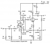
Perhaps the "best" implementation of Mullard style topology can be found in the H/K Cit. 5. Notice the high gm small signal types. The 12BY7 shown is getting scarce and is (IMO) best saved for already built units. A 6922 cascode that replaces the 12BY7 is provided.
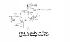
Hmmm... had to redraw, to wrap my brain around ''cascode''.
REV 2 - with GNFB, adjusted values. Thanks KodaBMX
Attachments
Last edited:
Hmmm... had to redraw, to wrap my brain around ''cascode''.
5 mA. is low, but a larger current requires a very "tall" B+ supply. Remember, this cascode is intended to replace the 12BY7 voltage amplifier in a H/K Cit. 5. The B+ rail is what it is, not the object of one's desire.
Stu Hegeman & Co. did not bypass the voltage amplifier's cathode bias resistor and I followed suit.
5 mA. is low, but a larger current requires a very "tall" B+ supply. Remember, this cascode is intended to replace the ¹²BY7 voltage amplifier in a H/K Cit. 5. The B+ rail is what it is, not the object of one's desire.
Yes, well then we agree. The 6922 is also expensive insofar as I can tell on the open market. Good (reputation) ones might run $25 to $75 apiece! That's pretty expensive as a cascode-in-one-bottle solution, which in the end, kind of emulates a small-signal pentode.
Stu Hegeman & Co. did not bypass the voltage amplifier's cathode bias resistor and I followed suit.
Yes, I know. But then I saw that KodaBMX posted a cute circuit with the prop-up style GNFB as per his (and then with REV 2, my) drawing.
Lastly, no quote, but a new thought...
The point of a non-capacitor-bypassed cathode resistor on a line-stage amplifying triode is to squash most of the C-bypassing-R triode ³⁄₂ power law response curve of the triode and ''tame'' it to something almost linear, at reduced gain (LNFB, effectively), and offering less ''tube 'color' '' to the amplified signal.
I generally agree with the sentiment, yet having somewhat greater gain when working the GNFB angle is also important. Hence why I included the C-bypassing-R cathode approach.
Just saying... GoatGuy
The EH 6922, which is in fact 6H23Π-EB (6n23p-ev), is very tough and exhibits decent, if unspectacular, sonics costs about $15. JJ's E88CC, is voiced more like the European OS that commands silly money. JJ does a better job on Noval than Octal and their E88CC costs about $16.
Jim McShane charges $19.50 for properly culled NOS GE JAN 12BY7s and the supply is dwindling. High gm makes both the 12BY7 and 6922 cascode quite different than a "run of the mill" small signal pentode. 12BY7 gm = 11 mA./V. 6922 gm = 12.5 mA./V. EF86 gm = 2 mA./V. Remember, for pentodes and cascodes stage gain is approx. = (gm)(net load).
Jim McShane charges $19.50 for properly culled NOS GE JAN 12BY7s and the supply is dwindling. High gm makes both the 12BY7 and 6922 cascode quite different than a "run of the mill" small signal pentode. 12BY7 gm = 11 mA./V. 6922 gm = 12.5 mA./V. EF86 gm = 2 mA./V. Remember, for pentodes and cascodes stage gain is approx. = (gm)(net load).
Many a successful Mullard topology amps have been built with a traditional triode for the input tube.
I built an amp using Edcor outputs and a 6922 input tube (not a cascode), and I was able to get about 14dB of NFB before the output transformers started to cause excess phase shift. At this point, however, the amp only had about 19dB of gain. This requires a reasonably hot preamp output to drive to full power. Expect to get a whole lot more than 14dB with the Fisher transformers, so you need a lot more open-loop gain.
I agree with Eli on avoiding the 12BY7- Existing HK Citations and many Amateur Radio transmitters are already eating up the existing stock. I'd look at other small-signal pentodes. A 12AX7 could work respectably as well. You can also use multiple gain stages if needed. In pentode mode, the driver tubes don't have to drive as much miller capacitance, so a slightly wimpier, higher-gain tube in the phase splitter/driver position could work acceptably well.
- Status
- This old topic is closed. If you want to reopen this topic, contact a moderator using the "Report Post" button.
- Home
- Amplifiers
- Tubes / Valves
- Selecting an output tube . . .