Edit: Links fixed--sorry!
Greetings All,
I've done a search, and not found a thread like this one, but if there is one, please point me to it and accept my apologies.")
I'm a semi-novice, am fascinated with CCS concepts, and have been studying everything I can get my hands and browser on, including Gary Pimm's "Active Loads and Signal Current Control article.
Now I'm semi-informed, have a specific application for his latest Self Bias CCS in mind, and would like to pester you all with some conceptual questions, to make sure I am beginning to understand. (Gary is certainly invited to chime in, if he is reading. )
1. Is it true that CCS varies the voltage at its output terminal ("MU" on Pimm's Self Bias CCS board) in order to try to maintain a constant current through that terminal?
2. Is it true that the voltage on that output terminal (MU) can only range up to the supply voltage (the voltage between the + and - terminals on the Pimm board)?
3. And here is the conceptual aspect I'm wrestling with:
Given #1 and #2, is there a point on the CCS-loaded flat loadline where, as Ug approaches cutoff voltage on the original slanted passive-resistor-load loadline, the CCS can no longer supply enough voltage to maintain constant Ia?
For example it seems to me that--looking at Gary's article's. original slanted (passive resistor plate load) loadline and extrapolating to Ug such that Ia = 0--at that point the full value of the positive voltage supply would appear at the anode, and there is nothing a CCS could do with the same Ug and supply voltage to maintain current flow, because the CCS cannot raise its output voltage above its supply voltage.
Correct?
Could this be why the first graph in the article does not show Ia=0 on the passive-load loadline, and the corresponding Ug on its CCS loadline?
Okay, I'll stop there for now, for I think that until I grasp CCS concepts well, any other questions that I might have will be more burdensome for obtuse than they absolutely have to be. : ) I hope these questions were relatively clear and painless.
Thanks for your time, and for any constructive comments that you might offer, so that we all might learn.
Best,
George Ferguson
Greetings All,
I've done a search, and not found a thread like this one, but if there is one, please point me to it and accept my apologies.
I'm a semi-novice, am fascinated with CCS concepts, and have been studying everything I can get my hands and browser on, including Gary Pimm's "Active Loads and Signal Current Control article.
Now I'm semi-informed, have a specific application for his latest Self Bias CCS in mind, and would like to pester you all with some conceptual questions, to make sure I am beginning to understand. (Gary is certainly invited to chime in, if he is reading.
)1. Is it true that CCS varies the voltage at its output terminal ("MU" on Pimm's Self Bias CCS board) in order to try to maintain a constant current through that terminal?
2. Is it true that the voltage on that output terminal (MU) can only range up to the supply voltage (the voltage between the + and - terminals on the Pimm board)?
3. And here is the conceptual aspect I'm wrestling with:
Given #1 and #2, is there a point on the CCS-loaded flat loadline where, as Ug approaches cutoff voltage on the original slanted passive-resistor-load loadline, the CCS can no longer supply enough voltage to maintain constant Ia?
For example it seems to me that--looking at Gary's article's. original slanted (passive resistor plate load) loadline and extrapolating to Ug such that Ia = 0--at that point the full value of the positive voltage supply would appear at the anode, and there is nothing a CCS could do with the same Ug and supply voltage to maintain current flow, because the CCS cannot raise its output voltage above its supply voltage.
Correct?
Could this be why the first graph in the article does not show Ia=0 on the passive-load loadline, and the corresponding Ug on its CCS loadline?
Okay, I'll stop there for now, for I think that until I grasp CCS concepts well, any other questions that I might have will be more burdensome for obtuse than they absolutely have to be. : ) I hope these questions were relatively clear and painless.
Thanks for your time, and for any constructive comments that you might offer, so that we all might learn.
Best,
George Ferguson
1. Yes
2. Yes
3. Real CSs have a limit on how much voltage they can supply to maintain the constant current. This is referred to as the compliance of the CS. In this case, it will be equal to something less than the supply voltage- i.e., the supply voltage minus the amount necessary to power up the CS, in this case the drop across R1 at the program current plus the sum of the saturation voltages of Q1 and Q2.
Here's a reductio ad absurdem: if you disconnect the bottom terminal of the CS from the plate of the tube, the current will clearly no longer be at the programmed value- unless, of course, there were sufficient compliance to cause a sustained arc!
Hi,
ROTFLMAO...
Syanide humour?
unless, of course, there were sufficient compliance to cause a sustained arc!
ROTFLMAO...
Syanide humour?
Hey SY,
Many thanks for your answers. You are kind to help me in my crawl towards understanding. Or perhaps a better analogy would be whipping a tired old horse until it responds.
Hey, great minds think alike. Or at least, great minds and mine.
For mental calesthenics, I was coming up with corresponding analogies for voltage and current, and yours was one of them--Current sources hate open circuits, and an ideal one would generate limitless voltage until an arc bridged the gap and restored the current. Voltage sources hate shorts, and an ideal one would generate limitless current until heat melted the short and restored the voltage. Perhaps that scene was deleted from Forbidden Planet?
I wonder what happens when an ideal voltage source meets a perfect insulator, or an ideal current source meets a perfect conductor? Time travel?
Thanks again,
George "Enthusiatic Amateur" Ferguson
Many thanks for your answers. You are kind to help me in my crawl towards understanding. Or perhaps a better analogy would be whipping a tired old horse until it responds.
SY said:Here's a reductio ad absurdem: if you disconnect the bottom terminal of the CS from the plate of the tube, the current will clearly no longer be at the programmed value- unless, of course, there were sufficient compliance to cause a sustained arc!
Hey, great minds think alike. Or at least, great minds and mine.
For mental calesthenics, I was coming up with corresponding analogies for voltage and current, and yours was one of them--Current sources hate open circuits, and an ideal one would generate limitless voltage until an arc bridged the gap and restored the current. Voltage sources hate shorts, and an ideal one would generate limitless current until heat melted the short and restored the voltage. Perhaps that scene was deleted from Forbidden Planet?
I wonder what happens when an ideal voltage source meets a perfect insulator, or an ideal current source meets a perfect conductor? Time travel?
Thanks again,
George "Enthusiatic Amateur" Ferguson
"Can God make a rock so heavy he can't lift it?"
Your conceptual model is a good one. Idealized models are often a good start toward understanding, but the scope of applicability of the model need always to be kept in mind. The real limitations in CS circuits are the actual made-good gain (which will be now heavily dependent on the grid resistor of the following stage) and bandwidth (which will now be even more heavily dependent on the input capacitance, "real" and Miller, of the following stage).
I'm not enthusiastic about CSs as plate loads in my own designs, but if I were to use one, it would be a heckuva lot simpler than the Pimm circuit and probably use bipolars.
Don't worry, one day you'll be as cynical and weary as Frank and me.
Your conceptual model is a good one. Idealized models are often a good start toward understanding, but the scope of applicability of the model need always to be kept in mind. The real limitations in CS circuits are the actual made-good gain (which will be now heavily dependent on the grid resistor of the following stage) and bandwidth (which will now be even more heavily dependent on the input capacitance, "real" and Miller, of the following stage).
I'm not enthusiastic about CSs as plate loads in my own designs, but if I were to use one, it would be a heckuva lot simpler than the Pimm circuit and probably use bipolars.
"Enthusiatic Amateur"
Don't worry, one day you'll be as cynical and weary as Frank and me.
"Can God make a rock so heavy he can't lift it?"
Yes, and no.
Your conceptual model is a good one.
Thanks! Having only one brain cell left, I give it regular exercise.
The real limitations in CS circuits are the actual made-good gain (which will be now heavily dependent on the grid resistor of the following stage) and bandwidth (which will now be even more heavily dependent on the input capacitance, "real" and Miller, of the following stage).
As I understand it, the Pimm circuit acts as a CCS *and* a mu follower, and can therefore supply relatively high drive currents while remaining in regulation. Is that true, and would that address your concerns?
Would that ability be worth the extra complexity?
(These questions are real, not rhetorical.)
Don't worry, one day you'll be as cynical and weary as Frank and me.
You think?


Best,
George "Brian Fellows" Ferguson
Hi,
Yes...but: maximized gain also maximises the Zout of this stage hence Sy's comments about g' and Cgk.
To my mind this is fine if you want to extract maximum gain from a tube while forcing it to stay into linear operation as for a first gainblock of a phonostage for instance.
IOW, I don't view this as a universal "cure all" , YMMV.
Cheers,
As I understand it, the Pimm circuit acts as a CCS *and* a mu follower, and can therefore supply relatively high drive currents while remaining in regulation.
Yes...but: maximized gain also maximises the Zout of this stage hence Sy's comments about g' and Cgk.
To my mind this is fine if you want to extract maximum gain from a tube while forcing it to stay into linear operation as for a first gainblock of a phonostage for instance.
IOW, I don't view this as a universal "cure all" , YMMV.
Cheers,
Hi,
That could actually be a good idea; a CCS loaded anode follower direct coupled into a CCS sunk CF...
Has anyone implemented that yet?
Cheers,
One technique sometimes used to get around the CS limitations is to direct couple to a cathode follower, then take the signal from there (a low impedance source).
That could actually be a good idea; a CCS loaded anode follower direct coupled into a CCS sunk CF...
Has anyone implemented that yet?
Cheers,
I tried this in a preamp linestage and in the input stage of a power amp back in the late '70s (inspired by Ike Eisenson), using 12AX7s and FET current source diodes. It worked, but didn't really get me any performance advantage in exchange for the complication. Haven't bothered since then.
fdegrove said:Hi,
That could actually be a good idea; a CCS loaded anode follower direct coupled into a CCS sunk CF...
Has anyone implemented that yet?
Cheers,
If you include the Bottlehead Foreplay with "Anticipation" C4S upgrade(CCS loaded VA stage direct coupled to CCS(ink) CF, then yes, hundreds of times.
If you include the Bottlehead Foreplay with "Anticipation" C4S upgrade(CCS loaded VA stage direct coupled to CCS(ink) CF, then yes, hundreds of times.
Thanks for reminding me, Pedroskova.
Some Foreplay owners swear by that mod.
Here's a link to a guy who has combined a Foreplay with the VTV 6SN7 and C4S.
Man, this stuff really fascinates me, and I have so much to learn before I can begin to understand and innovate. I think I need some more electronics education, but that's another thread...
Best,
George Ferguson
DrDeville said:
Hey! That's my preamp!... with one exception - I don't bypass the cathode resistor in the first stage.
Hi,
There's little use for it anyway; gain is maxed out due to the CCS load and you don't need the lower Zout as you couple into a CF.
All in all it should sound faster, crisper than a bypassed Rk.
You may want to bias the 6SN7 a little deeper though.
Cheers,
I don't bypass the cathode resistor in the first stage.
There's little use for it anyway; gain is maxed out due to the CCS load and you don't need the lower Zout as you couple into a CF.
All in all it should sound faster, crisper than a bypassed Rk.
You may want to bias the 6SN7 a little deeper though.
Cheers,
fdegrove said:Hi,
You may want to bias the 6SN7 a little deeper though.
Cheers,
Yep, but unfortunately, the little transformer is pretty maxed out, and the B+ sags pretty drastically after a certain point.
I've just finished the PSU for the "next generation" and it will allow me much more leeway. It will be a CCS'ed 76 tube driving a parallel- fed stepdown transformer.
It's the phono stage part of it that scares me to death: I'm getting a bad case of cold feet.

Hi,
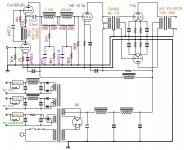
Here's something to help you get rid of those cold feet:
Cheers,
It's the phono stage part of it that scares me to death: I'm getting a bad case of cold feet.
Here's something to help you get rid of those cold feet:
Cheers,
Attachments
fdegrove said:Hi,
Here's something to help you get rid of those cold feet:
Helluva way to get rid of cold feet ---amputation due to frostbite.
pedroskova said:
Helluva way to get rid of cold feet ---amputation due to frostbite.
Surprisingly over-complicated for Frank. And so many overly expensive parts, too.
Hi,
Mom....They're teasing me again...
Actually, it's not my design at all....Sy's right, it's way too simple.
The RIAA LCR circuit is really one box per channel that you can buy from Lundahl and Sowter (or was it S&B?)....
It doesn't even cater for MC carts and it should have a S&B TVC to keep up the iron spirit...Which it doesn't...
Dang...Junk that thing.
Cheers,
Surprisingly over-complicated for Frank.
Mom....They're teasing me again...
Actually, it's not my design at all....Sy's right, it's way too simple.
The RIAA LCR circuit is really one box per channel that you can buy from Lundahl and Sowter (or was it S&B?)....
It doesn't even cater for MC carts and it should have a S&B TVC to keep up the iron spirit...Which it doesn't...
Dang...Junk that thing.
Cheers,
- Status
- This old topic is closed. If you want to reopen this topic, contact a moderator using the "Report Post" button.
- Home
- Amplifiers
- Tubes / Valves
- CCS Conceptual Qs, Using Gary Pimm CCS as Example