I want to build very simple OTL buffer to power >300ohm headphones with the best sound possible, if it means only needing 1 tube I can except not having gain.
Its mainly a question of the choice of tube, I currently have a pair of 5654 pentode tubes which are 120V. I could buy lower voltage tubes (<40V) and make use of an existing power supply, or I could buy a new trafo for 120V if there is any benefit to the higher voltage.
Im not sure if this a suitable choice as a 'power tube' or if 'power tubes' are a real thing or just describing the application, since transformers seem to be mainstay in a lot of tube designs.
this looks like the sort of thing if the first stage was omitted, but it uses a triode: DIY Audio Projects Forum • Information
Last edited:
Hi
I've just built a headphone amp for my Sennheiser hd600's based on a single triode strapped
Russian 2P29L dht inspired by a design on Ale Mogliaa,s Bartola Valves website.
This uses one of his hybrid mu follower loads for the tube to give a low o/p impedance with gain of about 8. The heaters are powered by Rod Colemans boards with SIC diode biasing. The anode voltage is 150V and anode current 20ma. So it will swing +/- 20ma into the headphones which is more then enough. Distortion is very low at about 0.02% and mainly 2nd harmonic.
It sounds superb much better than my other headphone amp,s like a battery powered JLH Class A.
The gain maybe too much for you. Because there is lots of gain I'm going to try using un bypassed resistive biasing of about 470R to try to reduce the gain a bit and provide some local f/b.
I also have some suitable 2:1 step down transformers to try in parafeed mode. This is for
other lower impedance phones.
Well worth considering . I dont think you would be dissapointed.
Member
Joined 2009
Paid Member
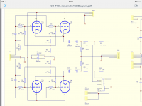
"You are not authorised to download this attachment."this looks like the sort of thing if the first stage was omitted, but it uses a triode: DIY Audio Projects Forum • Information
it would help if you could upload to this forum, I don't want to sign up for another forum just to see the picture.
Since nobody has answered your question, I'll give it a shot.
You can root around and find a set of 6AK5 triode curves, then derive what the transconductance is at some reasonable operating points (it actually looks quite promising). The tube is also listed as 20mA max cathode current.
I would run at least two per channel as triode strapped cathode followers running 18mA (shoot for 10,000uMhos of Gm at minimum). You can use a constant current source under the cathodes to set idle current, then bias up the grid a little bit more so you still have enough voltage under the cathodes to allow for adequate voltage swing at the output.
If you only want one tube per channel, there are other really common tubes that will work nicely.
Last edited:
If I were to try this exercise with just one tube, I'd probably find one of the big TV dual section compactron tubes in the big sweep tube thread, and just use up as much gain as possible from the small section to lower the output impedance of the big section used as a cathode follower output stage.
Building on my last post, could also use something like a 6AC10 triple triode, which has a respectable transconductance of 5800, and modify one of the 3-triode headphone amp designs like Aikido or Morgan jones-variant: The Morgan Jones Mini Tube Headphone Amplifier. – HeadWize Memorial
Metal conducts better than vacuum.
For decent power with low THD, you want the load to be 3-5 times the tube plate resistance. (For pentodes, the triode-connected plate resistance.)
A 300 Ohm load implies a 100 to 60 Ohm tube. There are no single tubes in this range, and certainly not small tubes.
People have used 6080, a 280 Ohm triode. They are pleased. So were the hearers of Edison's first cylinder recorder.
Transformers ARE your best friend, when vacuum tubes face wound motors (speakers including headphones, even 300r headphones).
I want to build very simple OTL buffer to power >300ohm headphones with the best sound possible.......
For decent power with low THD, you want the load to be 3-5 times the tube plate resistance. (For pentodes, the triode-connected plate resistance.)
A 300 Ohm load implies a 100 to 60 Ohm tube. There are no single tubes in this range, and certainly not small tubes.
People have used 6080, a 280 Ohm triode. They are pleased. So were the hearers of Edison's first cylinder recorder.
Transformers ARE your best friend, when vacuum tubes face wound motors (speakers including headphones, even 300r headphones).
sorry about restricted link, photo attached. there is also bottlehead crack , both use variations of same output tube, which PRR commented on.
thanks for other suggestions.
thanks for other suggestions.
Attachments
Last edited:
Gain is roughly 1/2 of the mu of the first tube.
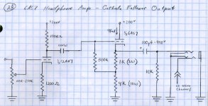
The circuit can run without gain with the addition of fixed biasing... This unfortunately adds a cap.
See attached.
Add a grid stopper if you want, but I've never needed it with this circuit. Also assume the same 620R/47u filter (which was based on an SMPS, and because I had the parts already. If you use a passive power supply, use 220uF instead.
Attachments
Last edited:
sorry about restricted link, photo attached. there is also bottlehead crack , both use variations of same output tube, which PRR commented on.
thanks for other suggestions.
A 12AX7 is a rough choice for that circuit. I note that it says 12A*7, but those component values suggest that the 12AX7 is the intended valve. The lower the gain the better for a circuit like that. The 12BH7 is a natural candidate.
Last edited:
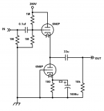
Not just a buffer since it has gain, but the finest OTL HP amp I've heard. It will drive 32R with a larger output capacitor (470uF)
The 6N6P is 30mA max operating current. Transconductance of the 6N6P will also limit performance into low impedance loads. Just increasing the coupling cap size is not the bandaid you're looking for. Taking that bottom triode and paralleling it with the top triode, then choke loading the whole cathode follower or just using a big resistor would be a step toward actually driving lower impedance loads.
Last edited:
It idles at about 20mA, it can swing about 40mA into the load. Also maximums are made to be exceeded  Plus this datasheet says 45mA http://tone-lizard.com/wp-content/uploads/2015/08/6n6p-6Н6П.pdf?048df8 and that means peaks of 100mA audio are within spec. In this case one tube swings up, the other down. Each 20mA for a total delta of 40mA.
This is enough for 50mW into 32R (plenty loud, and the earbuds that came with the phone sound like crap anyway).
Agreed though, it likes high Z phones better. My cans are 470R and in that case you might even want a 6N2P as first tube for "full volume" but a 12AT7 is a middle ground).
Plus this datasheet says 45mA http://tone-lizard.com/wp-content/uploads/2015/08/6n6p-6Н6П.pdf?048df8 and that means peaks of 100mA audio are within spec. In this case one tube swings up, the other down. Each 20mA for a total delta of 40mA.This is enough for 50mW into 32R (plenty loud, and the earbuds that came with the phone sound like crap anyway).
Agreed though, it likes high Z phones better. My cans are 470R and in that case you might even want a 6N2P as first tube for "full volume" but a 12AT7 is a middle ground).
Last edited:
Member
Joined 2009
Paid Member
I want to build very simple OTL buffer to power >300ohm headphones with the best sound possible, if it means only needing 1 tube I can except not having gain.
Thinking about using the one pair of 5654 tubes you have:
Your 5654 tubes have a gm of 5mA/V and if used as a cathode follower will have a Zout ~ 200R which you’ll apply 7x of loop feedback to in order to achieve a damping factor of at least 10 (a good target). A 12AU7 front end might work nicely.
You’ll need enough current at the output so run each tube at 15mA to stay below max rating which implies a plate voltage of 80V to keep away from max plate dissipation.
That 6AS7 option give you more grunt that the pentodes you own - an attractive option, but it sure has a greedy heater supply and transconductance is borderline for good damping factor (you may like the sound of a low damping factor).
Once you start down the road of using loop feedback you could consider using a transistor up front - as the gain element. It should be the natural choice as the output element given it’s high transconductance but I like the idea of using a BJT as the gain element and using the Pentodes you have at the output - appeals to me for some reason I can't explain.
I got a good price for 10 6n6P and always had building 2 amps for balanced drive in mind, to eliminate output caps and increase power.
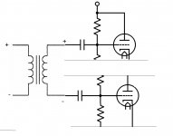
Is there any possible alternative to having the input cap on koda's buffer?
For example, the input to the amp will come from a DAC output transformer.
single ended you would have half the supply voltage across the secondary winding without the cap and the winding in parallel with the lower divider resistor, obviously a cap is needed there
for balanced it would be connected like the attached diagram, what would happen here if the caps were omitted?
Attachments
And increase damping factor and noise.I got a good price for 10 6n6P and always had building 2 amps for balanced drive in mind, to eliminate output caps and increase power.
You'll need to keep working on that schematic to the point where you believe it would be an operational circuit, then we can offer advise that's not so broad.for balanced it would be connected like the attached diagram, what would happen here if the caps were omitted?
- Status
- This old topic is closed. If you want to reopen this topic, contact a moderator using the "Report Post" button.
- Home
- Amplifiers
- Tubes / Valves
- very simple class A buffer for headphones?