Unfortunately I have to report, that a newly installed Philips QE08/200 tube in mint condition (so the seller told me), blew up!  It happened to the first design version on breadboard. The actual project is not operational yet, but the second one, mounted on a chassis is almost ready.
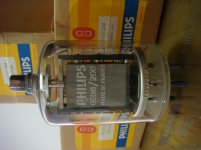
Now I`ve got some NOS power tubes from an old and very experienced radio technician, and exchanged them to check their state of health. The first power tube is a SRS461 (eastern germany made, in the past german democratic republic GDR), which stayed for a longer time in the amp. Today I put a Philips QE08/200 in mint condition (so I was told) in the amp - as second power tube for push-pull mode.
It was running very well, the tube was strong with good emission. I was playing music with a second tube amplifier, fullrange on broadband speakers. The monoblock was driving a 15" subwoofer with a passive crossover for the bass, just with a little load, nearly idle (in this video with an active crossover, recorded a few days ago). I listened to the music, and I was not alerted by some distorted sound or something other audible. Certainly the bass disappeard, but not noticeable.
So for about ~2 minutes I didn´t pay attention: but I was suddenly retrieved by some fireworks going up! - my first impression. The second impression was a burning amplifier in my dimmed livingroom, furiously scattering sparks around... ..and sadly recognized the bright white glowing Philips QE08/200 tube! Very astonished, I realized two choices: grap the phone and take a video...  - or to switch that thing out immediately! Due to the fulminant behavior, I switched the power off at first.... I recorded the video a few seconds after the fire had extinguished. The power tube was still glowing very bright and hot. It vented immediately, air came in and the getter material turned to white.
Now I have to do same investigation... And for the actual project which I build on a chassis, it means that I have to find constructive ways to intercept such a failure, and before it ends in such a way!
video: YouTube
It happened to the first design version on breadboard. The actual project is not operational yet, but the second one, mounted on a chassis is almost ready.Now I`ve got some NOS power tubes from an old and very experienced radio technician, and exchanged them to check their state of health. The first power tube is a SRS461 (eastern germany made, in the past german democratic republic GDR), which stayed for a longer time in the amp. Today I put a Philips QE08/200 in mint condition (so I was told) in the amp - as second power tube for push-pull mode.
It was running very well, the tube was strong with good emission. I was playing music with a second tube amplifier, fullrange on broadband speakers. The monoblock was driving a 15" subwoofer with a passive crossover for the bass, just with a little load, nearly idle (in this video with an active crossover, recorded a few days ago). I listened to the music, and I was not alerted by some distorted sound or something other audible. Certainly the bass disappeard, but not noticeable.
So for about ~2 minutes I didn´t pay attention: but I was suddenly retrieved by some fireworks going up! - my first impression. The second impression was a burning amplifier in my dimmed livingroom, furiously scattering sparks around...
..and sadly recognized the bright white glowing Philips QE08/200 tube! Very astonished, I realized two choices: grap the phone and take a video... - or to switch that thing out immediately! Due to the fulminant behavior, I switched the power off at first.... I recorded the video a few seconds after the fire had extinguished. The power tube was still glowing very bright and hot. It vented immediately, air came in and the getter material turned to white. Now I have to do same investigation... And for the actual project which I build on a chassis, it means that I have to find constructive ways to intercept such a failure, and before it ends in such a way!
video: YouTube
Last edited:
@Tony, once in a while I make use of various schemes, which are successfully rebuild by many amplifier builders, to combine and rearrange them for my requirements. So that success is given, instead of rebuilding unknown circuits somewhere from the net. I already made that mistake previously...
I like the german site jogis-roehrenbude very much, but I´m not shure if it´s allowed to directly link schemes from there. But I can tell you what I´ve done, the following documentations by Ernst Rößler were very inspiring:
Gegentakt-Verstärker in AB-Betrieb für EL34 / 6L6GC I use the G2 stabilization with a 6L6GB tube, like in the upper schematics about a Grommes 260A amplifier. That concept seemed nice to me. I wanted some tube rectification in my monoblock, even if there are a hand full of silicium bridge rectifiers for the auxiliary voltages.
The negative G1 voltages are realized like in the schemes, he calls: "Zunächst die Schaltungen des Parallel-Gegentakt-Amps und des angepassten Netzteils:" for preamplifier and phase inverter stage, the "PPP-Schaltung". It´s not stabilized with tubes, zener diodes or something else in my design. The voltage is delivered by a seperate winding of the transformer for the auxiliary voltages, and it´s not under heavy load. So I think it´s stable without any further circuits.
At first I thougt the glass of the blown up tube cracked somewhere because of the enormous heat. But it should be the gases that escaped out of the anode material, which are captured by the getter. The tube ist still working!
I finished the monoblock project on a chassis, the second one is working as an experimental setup on a breadboard. They work very well together in a stereo setup. There is so much power... literally breathtaking.
The whole thing is still under testing. The tube pairs still aren´t matched very well, and the right operating points have to be set properly. There is many fine tuning to do.
Please forget the -G1 operating points that I´ve said, with strong tubes they are much lower.
I have nine SRS461 / QE08/200 tubes, different health states. The range with these tubes is from 60 - 220mA anode current @ G2=250V, G1=-40V
I have to find the right tube pairs. But G1 will be every time lower than -40V.
I don´t get it at the moment, why some SRS461 / QE08/200 tubes blow up?!
I observed it exactly...
G2=250V is generated with the 6L6GB stabilization circuit.
This voltage is directed to both tubes. To prevent reverse voltage, I put a 1N4007 diode before G2 of each tube. So a defective tube isn´t able to increase voltage from it´s G2 for the other tube in an error case. It´s stable at 250V, no change in value.
G1 voltage is generated by a seperate transformer winding, bridge rectifier / capacitor, zener diode, voltage divider pot for bias balance. I monitore both -G1 volatges for the two tubes all the time, they are absolutely stable.
Now the magic happens:
Power the amp up. It runs stable for ~10 minutes. Then, suddenly: one tube increases it´s anode current. First slowly, the faster. The current grows immense, and if I don´t break the power, the tube blows up!
But! Not with every tube, and not in every combination. Some pairs of tubes work together, others not. The error changes with the tube if you swap them. G2=250V seems to have no effect when changing from 200-300V for the faulty tube, the good one reacts.
I don´t get it right now...
thanks @ketje
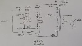
I generate the -G1 voltages with an own power supply. These two voltages go over 100k resistors to G1. Otherwise the signal level from the preamplifier stage is pulled down in the power supply. Like in the datasheet "AF class B amplifier" "operating condition two tubes" I count with Ig1 up to 1mA each tube, that is delivered by the power supply.
Please see my schematics attatched.
There are 150R protective resistors on G2, and a 1N4007 diode. Interesting: +250V from the power supply is measured (before the diodes), but directly on the tube pins G2 you can measure a much higher voltage, 350V for example!
That´s why I´ve put the diodes in, there is a reverse voltage from G2 back to the power supply. And I think this is the problem why some tubes blow up. They just don´t react to adjustment of +250V voltage.
My output transformer is primary 0,95k for each tube. To match the impedance, I set the transformer to 4 Ohms on the secondary and connect a 8 Ohms speaker. In many tests that gives the best results in output power.
Attachments
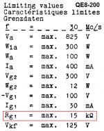
From my experience with the QE08/200 I learned that it is very sensitive to the value of grid leak resistors, especially when working with fixed bias. By experiment I found that the maximum value of the grid leak resistor should be 47kOhms, but for safety I installed a resistor much lower 27kOhms. Such a low value of the grid leak resistor requires that the driver stage has very little internal resistance.
The PHILIPS transmitter tube QE08/200 is designed for operation at relatively low voltage (max-825V!). The factory data does not have curves for triode connection, and since I could not find them on NET, I had to experimentally determine the initial output settings for the A1 SE-audio amplifier class. Available data indicate that the maximum voltage for G2 (in tethrode!) can be ~ 350V, but in a triode connection, the tube is stable at Ua-Ug2 of 500V!
The value of the G1 leakage resistor has been problematic, and for stable operation, it is necessary to keep a relatively low value compared to the normal values, at least when using a fixed negative bias. With values of ~ 50 kOhms (and larger ones, especially!), there would have starteed a backward emission and a gradual increase in current through the tube, which would ultimately lead to self-destruction of the tube.
The limit value of the G1 resistor stability ranged around ~ 45kOhms, but for stable, safe and long-term operation, it would need to use lower values. Although the electronics are foreseen for permanent work at anode dissipation of Pa ~ 100W (in triode connection probably more!), to prevent longer working life of the tube, I decided not to go with dissipation greater than Pag2 ~ 80W, which with voltage from Ub ~ 450 -460V results is a current of Ik ~ 175mA.
Existing output transformers can expect an output power of ~ 20W )more for maximum power!) but in practice the usable part is smaller (parametar is distortion up to ~ 2%). The low value of the G1 resistor requires low internal resistance of the driver stage (or more excitation power), so the choice of driver tube is limited. The intention to use the tube D3a-triode connected with its small internal resistance (Ri ~ 1,9kOhma) and high gain (~ 77x in ideal conditions, and in practice a little lower!) which excludes the need for more tubes.
Ik~175-185mA
Uak~455-465V
Pdis~80-85W
Pout~20-22W
Hi Tobi,
imo, a forward diode to G2 can be deleted, not sure if 220 ohms in series is a good value...
nice inputs, G1 grid leak of 10k is seriously considered, 27k seemed to work, these are invaluable tips to consider....
inductance in the grids? i have had not so good results with those is the 6C33 grids...i used carbon composition resistors in that spot...
your opt with a dc resistance of 0.95 ohms and Ik of 185mA gives you a loss of 175 vdc, i think that is too high....
others may comment about this...i want to be corrected....
... 100k resistors to G1. Otherwise the signal level from the preamplifier stage is pulled down
You can't cheat Rg1 (much). If the datasheet says 15k, USE 15k. If you need a stronger driver, build a stronger driver.
Like in the datasheet "AF class B amplifier" "operating condition two tubes" I count with Ig1 up to 1mA each tube
Since you have a coupling capacitor to the grid, the class B(2) conditions do NOT apply. You can not force 1mA of DC through a coupling cap. You *can* have 1mA of DC grid current from gas or ionization in a hot tube. Working in 100k, this is a 100 Volt shift of grid bias. That can not be good.
+250V from the power supply is measured (before the diodes), but directly on the tube pins G2 you can measure a much higher voltage, 350V
Yes, some tet/pentodes can have negative screen current under some conditions. You do NOT want the G2 to "float up". Lose the diode. If your 250V supply can not *absorb* the negative G2 current, use a bleeder or other trick so the G2 voltage never floats up.
A small (100r-1k) G2 resistor has little effect most of the time but may reduce G2 abuse in extreme conditions. Guitar amplifiers often use G2 resistors.
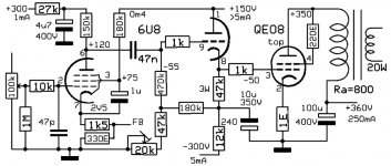
Perhaps the safe way to drive that tube is with a cathode follower.
Something like this (didn't try it) should give an input of around 300mVtop without FB.
Best to turn on the supply after the 6U8 is warmed-up to prevent allmost -300V between heater and cathode (heater at ground level).
Mona
Something like this (didn't try it) should give an input of around 300mVtop without FB.
Best to turn on the supply after the 6U8 is warmed-up to prevent allmost -300V between heater and cathode (heater at ground level).
Mona
Attachments
- Status
- This old topic is closed. If you want to reopen this topic, contact a moderator using the "Report Post" button.
- Home
- Amplifiers
- Tubes / Valves
- SRS461 | QE08/200 Monoblock Amps