If I would need something to drive 600ohm I see a few options.
-something with a 12BH7 as kathode follower can work I think
Sure, it can.
Wavebourn - Testing the preamp. I am pleased, the result... | Facebook
I've been working on a 6P15P spud headamp using Antek 10VA toroids in a parafeed configuration as the output transformers. The frequency response is flat from 10Hz up to the limits of my signal generator, which is around 160KHz. Wiring the transformer to 230v to 10v gives a reflected load around 29K ohms with my 55 ohm headphones. Granted, I'm throwing voltage gain away, as my cans really only need a buffer, it does sound very good for using $10 OPTs. I've measured the distortion around .1% at deafening levels (1Vpp input) all second harmonics.
Parasitic capacitance is usually an issue with toroids, but the lower winding ratio required for 600 ohm headphones should minimize this if you tie the primaries and secondaries in series. Biasing your output tube with sufficient current will overcome any slew rate issues as well. I'm idling at 50mA, which is overkill, especially for my machinist ears.
Parasitic capacitance is usually an issue with toroids, but the lower winding ratio required for 600 ohm headphones should minimize this if you tie the primaries and secondaries in series. Biasing your output tube with sufficient current will overcome any slew rate issues as well. I'm idling at 50mA, which is overkill, especially for my machinist ears.
Lots of great ideas, and one bad one:
Antek Toroid - I love it for three reasons:
1. Configurations - there are 11 different turns ratios available
2. Availability - most are in stock
3. Price - $10 for 10VA, a whopping $1 extra for 25VA, and 50VA is $17.50
And I built the isolation transformer for my workbench around a much larger Antek toroid
Cathode Follower - mixed review:
1. a twin triode in socket is competitively priced with even $10 transformers
2. I do not know how to tune distortion with a cathode follower, can anyone suggest links to explanations?
Heresy - Resistance coupled
1. As expected, efficiency is very low. I calculate the following voltage gains using 600 Ohms for resistor Rs:
Type 85 0.8
12SL7 1.3
12SN7 1.3
6L6 triode 1.9
2A3 2.8
6L6 pentode 4.6
The wretched amplification value of 4.6 is all that I need for headphones. What am I missing?
Question re: headphone amp design using cathode follower output...
How many volts does the amp need to cleanly swing into a 300 ohm load? Into a 600 ohm load?
Using the specs for the 320 ohm Sennheiser HD650 as an example, its sensitivity was measured at 90dB SPL for 0.206V rms out from amp. 0.206V rms into 320 ohms equals 0.13mW of power.
Assuming the power output must double for each +3dB SPL, if I wanted to make sure I could reach 108dB SPL peaks, that would mean about 8.5mW max output would be necessary for this 320 ohm headphone.
1.65V rms into 320 ohms = 8.5mW, so is that a useful target for max output from a headphone amplifier designed for this 320 ohm headphone? That comes out to 2.3V peak out from the amp.
For 600 ohms, if the headphone in question has sensitivity of 90dB with 0.512V rms input (taking Beyerdynamic DT880 as an example):
90dB at 0.5Vrms into 600 ohms = 0.43mW
Assuming the power output must double for each +3dB SPL, 27.5mW would be necessary to reach 108dB SPL.
If so, that's about 4V rms out from the amp (about 5.7V peak).
So if I'm looking to reach 108dB peaks cleanly with these example headphones, I'd want an amp that can deliver 2V rms into 300 ohms and 4V rms into 600 ohms, correct?
Since 1V rms is the max output from an iPhone or USB bus-powered DAC, then a gain of 4 is the minimum. A little extra wouldn't be bad, so let's say a gain of about 6 (+16dB) to 8 (+18dB).
No?
--
If we are talking 1.4 to 3.5 Watts power output, just-check-datasheets, coupling that to headphones will burn them, make you deaf and if you insist maybe melt your brain.
Just sayin´
I agree. Two 6L6 is pushpull is too much power for a pair of earphones. Why not to try some lower power units, for example, a copule of 12AU7's, 6DE7's, 6FM7's, etc?
...The data sheets for the 2A3 and 6L6 which follow show that the 3rd harmonic (which I want to minimize) increases with increasing load on the pentode, and is reduced by increasing load for the triode:
https://frank.pocnet.net/sheets/127/2/2A3.pdf
https://frank.pocnet.net/sheets/127/6/6L6G.pdf...
The 2A3 sheet says no such thing. OK, maybe the trace rises a hair above 3.5k, though this may also be a crooked T-square or just measurement slop.
*IF* the 3rd rise at high Z, it is usually because the tests were run at HIGH signal level. 2A3 was run at -45V bias, 31.8V swing. Which is 44.52v swing, and probably near significant grid current. The 6L6 data is 14V bias and 10V signal, "slammed".
If you had an actual 3rd THD spec to meet, you would *turn down* from this extreme (power output boast) conditions and 3rd would fall right off.
I can't imagine needing 15W-19W tubes to drive headphones. Is your house cold? However running a 5 Watt amplifier at 0.05 Watts should put your THD way-way down.
If you are concerned with numeric THD, you need NFB, which is simple to implement.
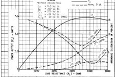
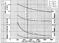
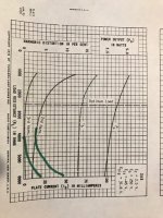
Here are curves typical of those which stimulated my question.
The first shows a typical pentode with 3rd harmonic increasing with increased load. The second shows a typical triode with 3rd harmonic decreasing with increased load.
When a pentode is triode strapped does the curve for the 3rd harmonic swing up on the left like a triode or on the right like a pentode? (these curves seem typical, and would be much the same for 6Y6, 6L6, 6V6 etc.)
Attachments
You're loosing time...just build something that was already tried because the headphones themselves have very different response from one to another.Just look for an amp that electrically is right for the load.Later you can deal with the harmonic content from a preamp or just by series loading of a resistor with the headphones or with the primary of the transformer.
Here are curves typical of those which stimulated my question.
The first shows a typical pentode with 3rd harmonic increasing with increased load. The second shows a typical triode with 3rd harmonic decreasing with increased load.
When a pentode is triode strapped does the curve for the 3rd harmonic swing up on the left like a triode or on the right like a pentode? (these curves seem typical, and would be much the same for 6Y6, 6L6, 6V6 etc.)
You did not get the point.
When load impedance (r) increases, the swing of anode voltage increases (gm*r); so the tube starts saturating unless you increase B+ accordingly. When swing increases the saturation gets more symmetric, all distortions increase, except even order ones that decreases due to symmetric saturation. Simple math, Fourier transforms. No magic here essential to the particular tube.
Another thing to keep in mind when increasing the reflected load is you wind up decreasing your voltage gain from your winding ratio. You have to compensate the higher stepdown by driving your output stage harder, increasing distortion. I noticed this with my current breadboard. By wiring the secondaries in parallel, my reflected load was over 100k, but the distortion was higher due to the higher drive requirements. Your best bet, I believe, would be to find out the drive requirements for your headphones. From there you can find an appropriate turns ratio that would deliver sufficient power with a bit of headroom when plugged into your preferred source. There is a point of diminishing returns in my experiments. In fact, if I further reduce the stepdown ratio (and the reflected load), I very well could get the distortion lower. But at that point, I would be risking damage to my cans from the increased deliverable power.
I did not damage my Tascam studio cans when tested the amp that delivers 8W on 32 Ohm.
However, I did that shortly, and not on the full power; enough to hear them loud, like a speaker.
Wavebourn - Testing headphones... | Facebook
However, I did that shortly, and not on the full power; enough to hear them loud, like a speaker.
Wavebourn - Testing headphones... | Facebook
One of my best amps for headphones is actually Kenwood A63...2x30w/8 ohms which runs the headphones output directly at the output of the power amp.That's as good as TPA6120 in terms of dynamics but it's even cleaner, lower noise i mean! I run it with the volume at 10%...it has very low noise transistors all throughout, but it's all about the cleanest sound you can get, not about harmonics...
Mine actually started out as an experiment to see how small of a parafeed coupling capacitor I could use in a headamp. I wanted to use silver micas initially, but the largest I could find was .1uF. The plate load is a cascoded CCS, and I use a screw type terminal block for cap rolling. The higher the reflected load, the smaller the parafeed cap. Up until recently, I was unable to acually set up a lab for measurements (I lived in a studio apartment for a number of years). Now I use the amp as my guinea pig for learning how to take proper measurements. Come to find out, I actually prefer small amounts of harmonics. I've also learned nothing beats hands on experimentation.
Never use line transformers for tube amplifiers.
10Vrms, and minimal bias = disaster for headphone amp
P.s. I am not an headphone fan, I don't see the point of headphone amps. Any good computer chip is able to drive headphones very well, including 600 ohm , many audiophile computer boards have the capability.
My experience, I built 3 headphones amps, cathode followers, and one from Glassware, which is maybe the best you can build, possible transformers with S.E.T. could be better...
Note: headphones hate DC, they hate Ripples.
So.... my question for you, what do you plan to amplify, the garbage out of your dac? or you plan to build an integrated design?
Did you hear the Meridian Director?
This is fun!
As a newcomer to valves I have asked many questions on this forum, some less clever than others, but I have rarely provided answers.
I had questioned the relationship between load and distortion for a triode-strapped pentode. The typical data sheets show graphs of this relationship for trodes and pentodes, but not for strapped pentodes. The triode curves show distortion increasing at low loads but never at high loads, but the pentode curves show increasing distortion at both low and high loads.
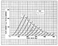
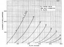
The answer is distortion for a strapped pentode increases at both high and low loads. The three attachments show two plate characteristic curves (first for a real triode and then a triode-strapped pentode) and then an abstract sketch of the resulting relationship between distortion and load.
Note that in the horizontal axis the load lines for the real triode are evenly spaced, and therefore rotating the load line horizontal (higher load) will not increase distortion. However for the triode-strapped pentode the load lines are compressed on the right, so as the load line is flattened distortion will increase again, somewhat like a normal pentode.
Yes the math is easy, but a graph is worth a thousand algorithms and helps me quickly visualize the general relationships.
And yes this is wasting time. But this is a road-trip where the objective is discovery. The interstate highways and drive-through windows are to be avoided. If the result is eventually a headphone amp, that is also OK.
As a newcomer to valves I have asked many questions on this forum, some less clever than others, but I have rarely provided answers.
I had questioned the relationship between load and distortion for a triode-strapped pentode. The typical data sheets show graphs of this relationship for trodes and pentodes, but not for strapped pentodes. The triode curves show distortion increasing at low loads but never at high loads, but the pentode curves show increasing distortion at both low and high loads.
The answer is distortion for a strapped pentode increases at both high and low loads. The three attachments show two plate characteristic curves (first for a real triode and then a triode-strapped pentode) and then an abstract sketch of the resulting relationship between distortion and load.
Note that in the horizontal axis the load lines for the real triode are evenly spaced, and therefore rotating the load line horizontal (higher load) will not increase distortion. However for the triode-strapped pentode the load lines are compressed on the right, so as the load line is flattened distortion will increase again, somewhat like a normal pentode.
Yes the math is easy, but a graph is worth a thousand algorithms and helps me quickly visualize the general relationships.
And yes this is wasting time. But this is a road-trip where the objective is discovery. The interstate highways and drive-through windows are to be avoided. If the result is eventually a headphone amp, that is also OK.
Attachments
As someone who also enjoys the journey of learning everything he can about tubes, I can tell you that you are jumping down the wrong rabbit hole with all this information.
By the time everything is said and done, tube distortion will not matter all that much. Its not that distortion isn't important, but you will end up finding out that there are other problems that are worth more of your time. For instance I think bandwidth will be much more of an interesting problem for you to solve than tube distortion. And just wait until you learn about transformers and all the issues they have.
In any case, I would forget about pentodes. Pentodes are just going to have way too much power for your application. And yeah, you can triode strap a pentode, but why bother? If you want a triode, just use a triode. You can come back to pentodes when you want to make a speaker amp.
I think you should look at using 6asg7/6080 tubes. It uses two power triodes in the same bottle. You can parallel them to make a single power triode tube. You can use them in push pull. The plate impedance is really low and you can use them as an OTL amp. They are currently still in production and are really cheap. You can basically experiment until your heart is content.
I think you will end up finding out that circuit topology matters wayyyyyyyyyy more than anything you can find in a tube data sheet.
Last edited:
Triode strapping a tetrode is a great way to get a linear tube with a low cost, and in some cases (like sweep tubes) there simply isn't a triode made that compares. 6P45S triode connected for instance, has a mu of about 3.3, and an rp <300R but can handle 400mA steady state current with peaks to over 1A. A 300B can't do that and costs several times more money. As far as the OP is concerned, they could probably use EF86 tubes for headphones since the power requirement is so low, but I still prefer the OTL amp I posted earlier in the thread. As far as the 6080 goes, it's not very linear, hard to drive, and is expensive to heat. It makes a good pass tube but that is what it was designed for, right?
I think I need glasses. This whole time I thought the 6as7g was linear. I put the plate curves in MS paint and drew some lines, and sure enough its not a great tube.
Well crap. It would have been a really nice tube for the op because he would have been able to do darn near every topology he has talked about.
And yes, triode strapping a tube is not a terrible practice, but for a headphone amp, I sort of feel like its pointless. I mean you can literally use a single 6c45pi in a spud style amp and it would still be more than enough.
- Status
- This old topic is closed. If you want to reopen this topic, contact a moderator using the "Report Post" button.
- Home
- Amplifiers
- Tubes / Valves
- output transformer for 600 Ohm headphones